Overview
Industrial PAPRs can provide clean air with very low breathing resistance. However, most PAPRs are heavy, noisy, and expensive. What if a lightweight “residential” PAPR for home and office use can deliver the same level of clean air for a fraction of the weight, noise, and cost?
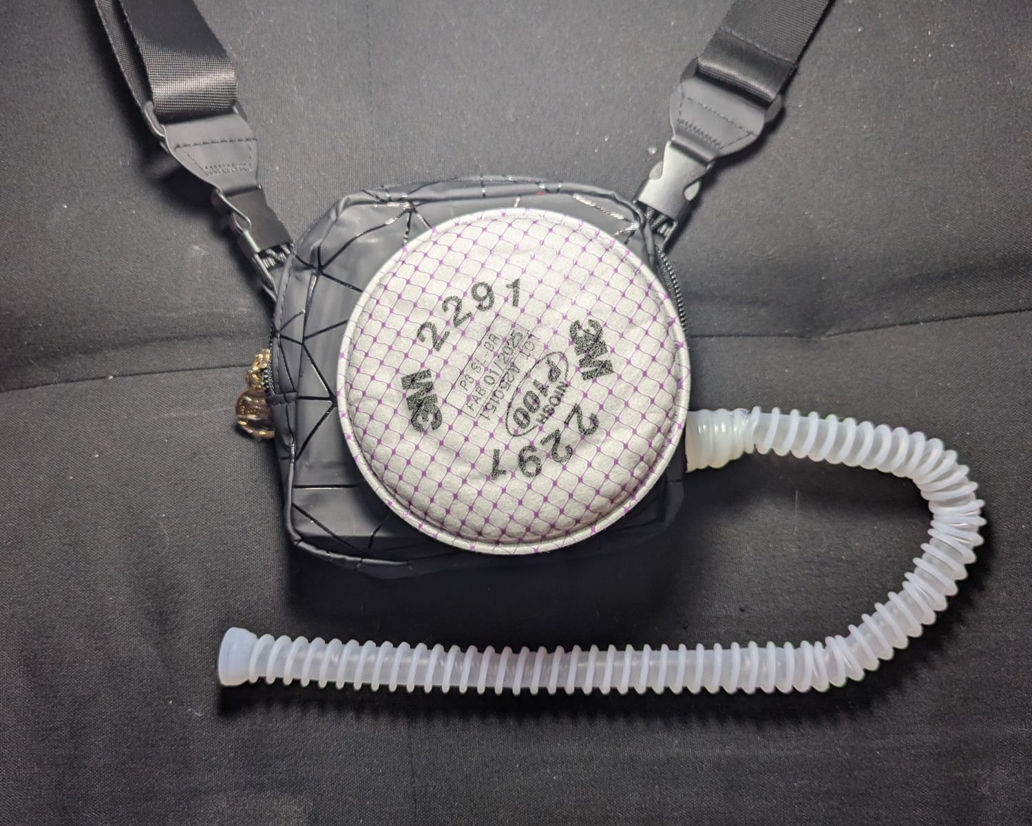
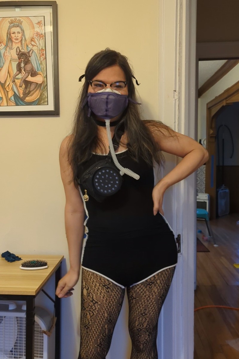
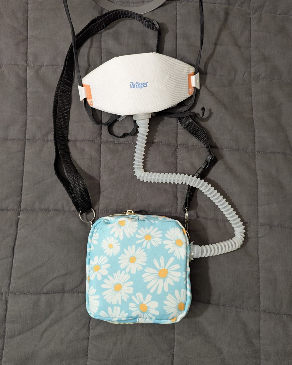
This DIY PAPR attaches to your N95 (or better) to lower breathing resistance, eliminate moisture (whether in humid or cold weather), while increasing overall filtration efficiency without the noise, weight, or cost of an industrial/commercial PAPR. The device pairs with a source-controlled N95 to protect the people around you, and it’s constructed from replaceable parts, so it’s easy to repair.
“Residential PAPR” has a nice symmetry when shortened to “rPAPR” and hints at a lighter (but still tremendous) protection level that can be worn at home, the office, concerts, and parties. It can also be worn to the dentist when combined with a ReadiMask.
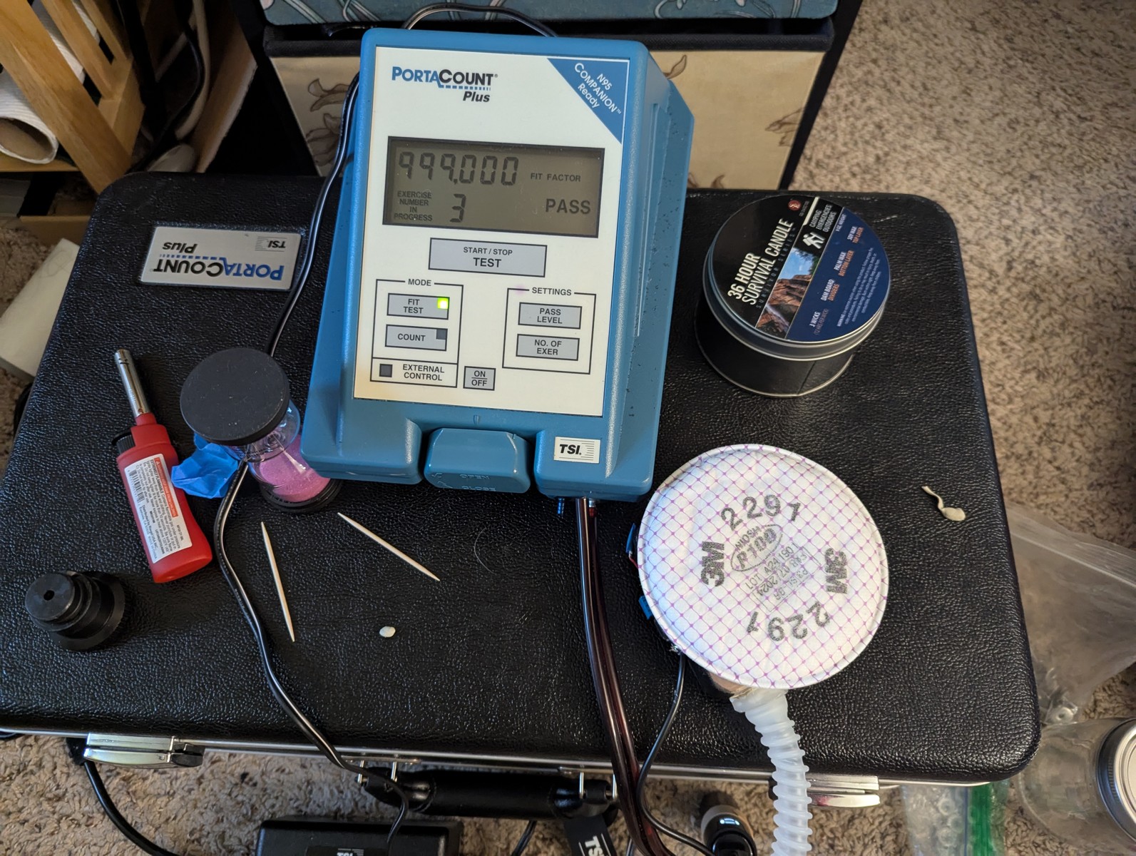
Check out these fit scores.
For comparison, the typical 3M Aura (N95) registers 200-300 fit factor on the PortaCount 8020A
| DIY PAPR + Drager X-Plore 1950 M/L (2 Weeks Old) | 3M 2291 | 3M 2291 |
|---|---|---|
| NIOSH test | Fit factor | FF (Unpowered) |
| Normal Breathing | 394000 | 247 |
| Deep Breathing | 379000 | 327 |
| Left right | 377000 | 326 |
| Up down | 123000 | 328 |
| Grimace | 119000 | 184 |
| Talk (Whisper only) | 10800 | 150 |
| Bend | 344000 | 396 |
| Normal Breathing | 415000 | 405 |
| Overall | 65428 | 264 |
(Fit factor is a measure of how much cleaner air is inside the mask than outside, by particle count.)
In the event that the device loses power, it still protects. The unpowered rPAPR extends the N95 and filters passively even when the blower is off.
This design uses 3M bayonet filters, which have excellent quality control, performance, variety, and availability. Most hardware stores carry them.
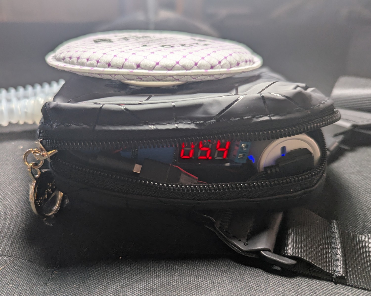
This design has adjustable flow: low for the office and at home, and high for exercise. Shown below are the case internals, with battery and voltage adjustment.
Warning
- The residential PAPR must be combined with a well-sealed N95 or better.
- Air flow is not enough to power a loose-fitted hood as with an industrial PAPR.
- Loose-fitting KN95s will work with the residential PAPR, but with modest results. When unpowered, protection will fall back to the KN95 alone.
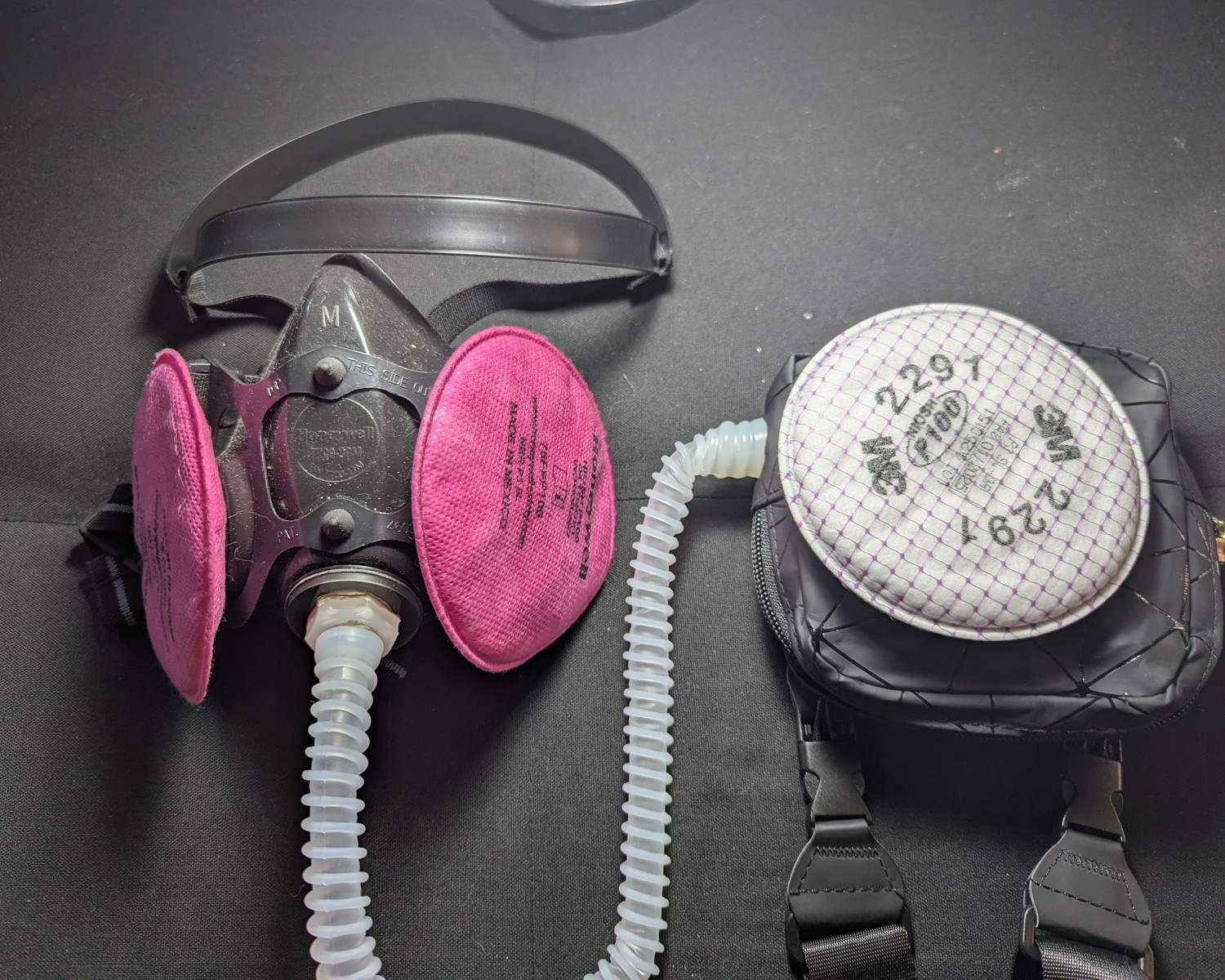
Want to get “industrial?” You can connect the rPAPR to a Honeywell North 7700 Series half mask respirator for source control! (Instructions at the end.)
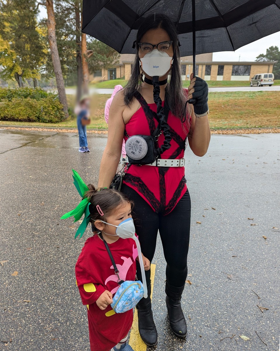
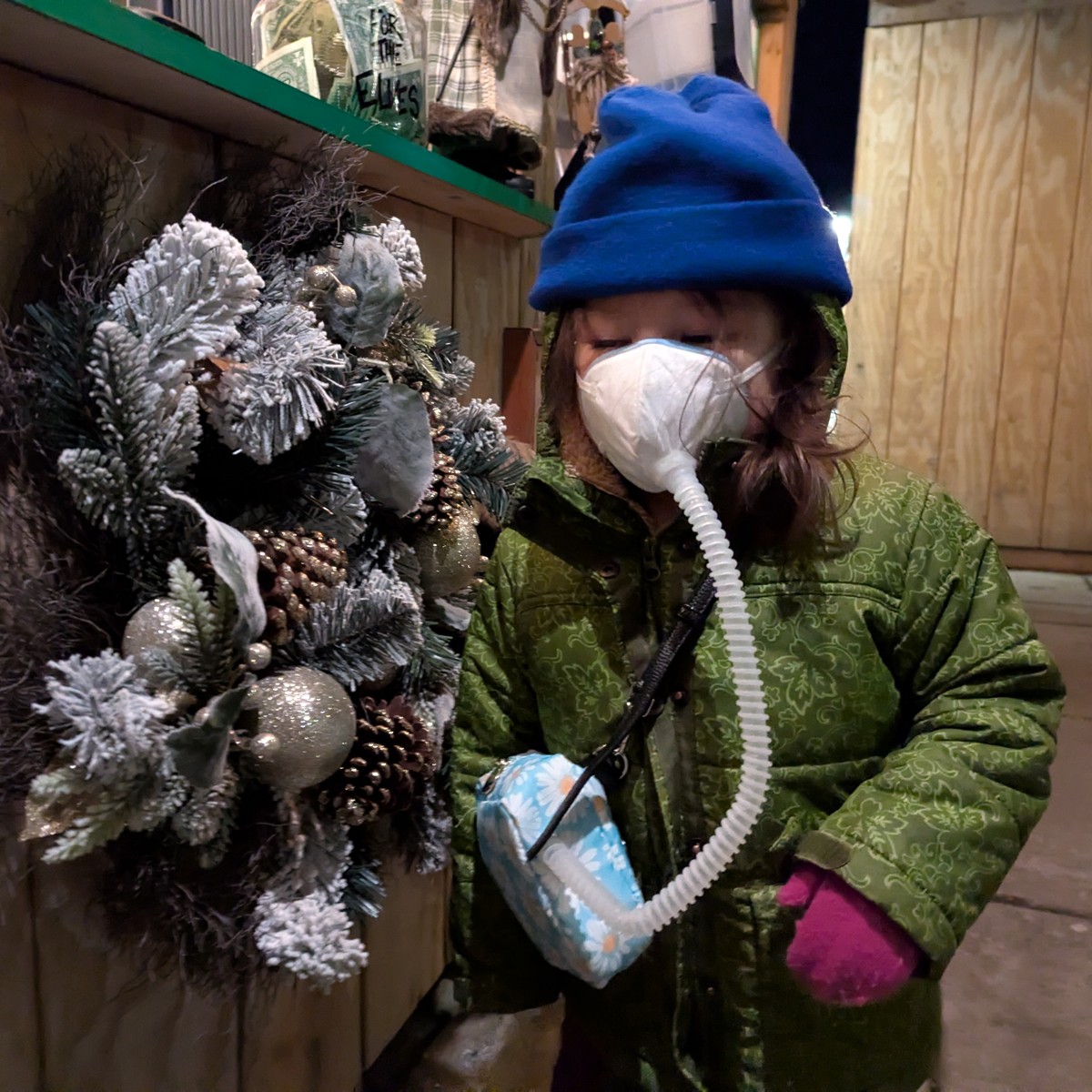
It’s also worth mentioning that powered masking has reduced the friction for masking uptake among kids.
Very often, only KN95-level protection is available for toddlers, but when combined with a powered filter like the rPAPR, their protection level can be brought up to an adult’s.
But how does it feel?
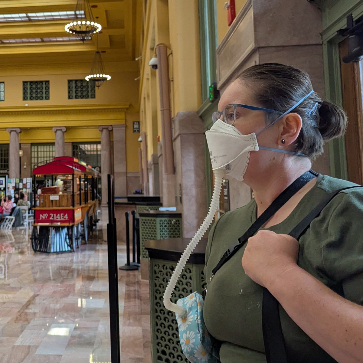
In my day-to-day, this setup has replaced all masking setups whether indoors or outdoors. I no longer keep separate masks for separate scenarios. It’s simply the most breathable mask setup I have. On days below freezing, moisture doesn’t build. I can stay comfortable masking all day, even at the mandatory full day in the office.
Discussion on fit test results
When fit testing friends with the rPAPR, the results are lower for deep breathing. Deep breathing overcomes the clean air delivery rate of the blower, bringing the masking efficiency to baseline. You can think of your lungs as a high capacity bellows. Industrial PAPRs must blow at high levels to handle the few cases where you have to breathe deep.
| DIY PAPR + JedX FFP3 | 5.3 v | 6.0 v |
|---|---|---|
| NIOSH test | FF | FF |
| Normal Breathing | 114000 | 435000 |
| Deep breathing | 448 | 940 |
| Left/Right | 30300 | |
| Up/Down | 4890 | |
| Grimace | 84600 | |
| Talking | 385 | 889 |
| Bending | 134000 | |
| Normal breathing | 31600 | |
| Overall | 1560 |
Talking alters the dynamics of the rPAPR in a similar way. In order to talk, we take in gusts of air that’s similar to deep breathing. The whisper-only talking test attempts to control for this and test only the effects of the mouth and jaw movements.
Even then, we can see a reduction in the fit score. These can be attributed to the seal of the mask. The 10,000-or-so fit score seen in the first table is still impressive, yet it may indicate micro-compromises in the seal that are “patched” by the positive pressure inside of the mask.
All this to say that the results are highly dependent on having a good, well-sealing N95. Bifold KN95 masks don’t fare as well. On its highest setting, the best the rPAPR can do is to get it up to 3M Aura levels. For many, this is a considerable improvement. For most, however, just wearing the 3M Aura would be a lot less trouble and expense.
We have found that increasing the flow rate helps restore some of the filtration efficiency that’s “lost” when deep breathing. For physical activity like dance classes, it’s worth dialing up the input voltage to 5.7 v or 6.0 v.
Table of Contents
Safety Disclaimer
The following instructions are provided as-is and free of charge for informational purposes only. The author assumes no responsibility or liability for any issues, damages, losses, or injuries that may result from the construction, use, misuse, or inability to use this device or these instructions. This includes, but is not limited to, health effects, exposure to fumes or materials, mechanical failure, electrical hazards, or unintended consequences of operation. The device is used entirely at your own risk. No guarantees are made regarding safety, performance, completeness, or suitability for any particular purpose. Users are responsible for ensuring proper materials, safe construction practices, adequate ventilation, and compliance with all applicable laws, regulations, and safety standards. The author is not responsible for errors, omissions, or changes in conditions, materials, or user capability. By using these instructions, you acknowledge and accept full responsibility for all outcomes related to the device.
Materials and Cost
Refer to the Materials Page for a breakdown of materials, costs, and suppliers.
There are two columns for cost: individual and bulk. In most if not all cases, you can only buy in bulk. The individual column is provided for those who want to make multiple rPAPRs, and to provide a cost estimate for commissions.
Adhesives are listed in the bulk column only.
Batteries are the most expensive component, and as of 2026/2/16, prices are skyrocketing. I’m researching use of 18650 cells, but at this point I can’t recommend any alternatives.
Tools
- Power drill and bits
- Drill bits
- Step drill bit
- Rotary tool with cutting blades
- Soldering iron
- Automatic wire stripper (manual not recommended)
- Scissors
- Adjustable wrench
- Box cutter
- Screwdriver
- PortaCount 8020A
Optionally:
- 13 mm hole punch (for quickly installing the hose adapter to the N95)
- Rubber mallet
- Sewing kit (If sewing on the D-ring attachments for the strap)
Detailed Instructions
Use these instructions to make your own rPAPR.
These instructions only cover the exposed version of the rPAPR:
However, a “sheltered” version can be constructed, which faces the filter inward, towards the body. To make this, a thicker pouch is needed, available here.
The differences between these two variants:
| Exposed | Sheltered | |
|---|---|---|
| Nominal Voltage | 5.3 v | 5.7 v |
| Battery Life | 8 hours | 6 hours |
| Filter replacement | Easy | Cumbersome |
| Filter type | All 3M bayonet filters | Only pancake filters |
In lieu of making the sheltered variant, you can use a filter cover for the exposed variant can be constructed.
This is a difficult build. You will need power tools, soldering, and precision. Care must be taken to properly seal the blower unit which sits inside the case. Some electronics knowledge is needed.
To test the rPAPR, you will need a particle counter, such as the PortaCount 8020A.
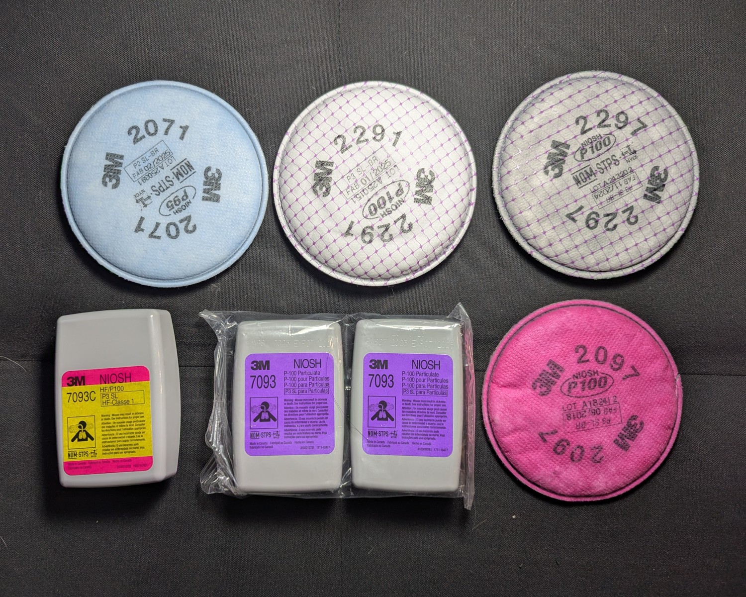
Select the Filter
The blower unit must be tested at several points in the build using a PortaCount. It’s helpful to commit to a filter type early so you can have one on hand for your tests.
| Filter Name | Characteristics |
|---|---|
| 3M 2071 - “Blue Pancake” | The highest air flow. Decent filtration efficiency. Lowest profile. |
| 3M 2291 - “White pancake” | Good balance of air flow and very high filtration efficiency. |
| 3M 2297 - “Gray pancake” | Same as above with a carbon layer for nuisance level organic vapor. |
| 3M 2091 - “Pink pancake” | Wider availability, but lower air flow than the 2291. Same filtration efficiency. The 2291 is superior. |
| 3M 2097 - “Pink pancake” | Same as above with a carbon layer for nuisance level organic vapor. |
| 3M 7093 - Cartridge | Okay air flow. Lowest measured filtration efficiency. Cannot be used in the sheltered version. |
| 3M 7093c - Cartridge | Same as above with a carbon layer for nuisance level organic vapor. |
In normal conditions, the pancake filters outshine the pleated cartridges thanks to the electret material, which helps to filter below 0.3 micron. However, this advantage disappears when wetted (and reappears when dry, since as the name implies, the electret is like a magnet but for electric charge). For rainy, humid, or oily conditions, the 7093 cartridges are better, albeit at much lower baseline filtration efficiency because of the non-charged mechanical nature of the pleated filtration media. Generally speaking, use the pancakes for indoor use, and cartridges for outdoor use.
Avoid organic vapor cartridges
People have shown interest in this build to avoid exposure to airborne respiratory infections like SARS-CoV-2 (covid).
Organic vapor cartridges like the 3M 6000 series do NOT filter particulates, and are thus ineffective for SARS-CoV-2, viruses, dust, or allergens.
Smoke
While the device has been tested for light smoke and second-hand cigarette smoke, the filters will not survive heavy smoke exposure as from a fire pit. Prepare to change the filter if exposed.Maintenance: Filters must be changed when flow rate gets low, about twice a year or more for home and office use.
Avoid touching the filter material. If contact is a concern, consider either the 7093/7093c, or using a filter cover. Alternatively, the “sheltered” version of this build faces the filter towards the body and hides it inside the case.
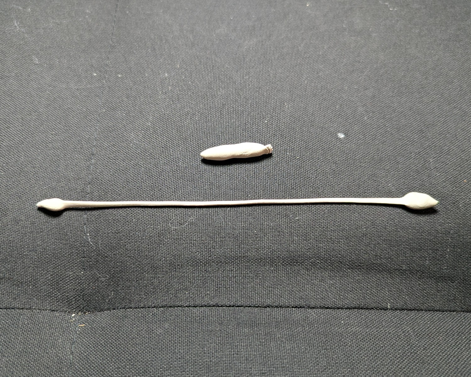
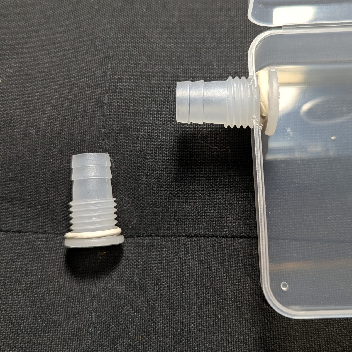
Make the hose fittings
Use a rotary tool, Dremel, or saw to remove the non-threaded half of 2x bulkhead hose fittings. These fittings form both ends of the intake hose. One fitting will be used for the rPAPR’s hose adapter. The other will be installed inside the mask.
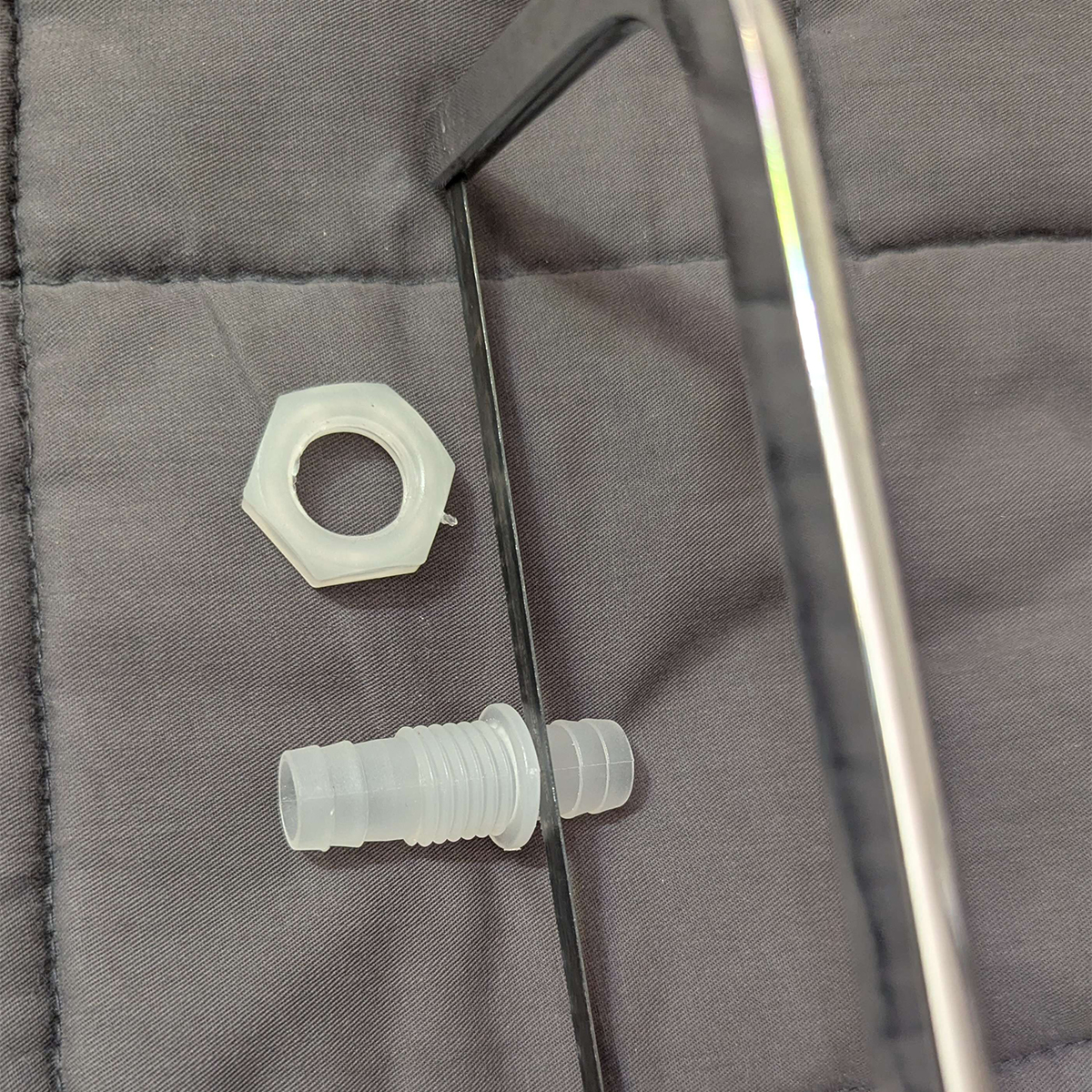
Refer to this page for more detailed info.
Make the Blower Unit
Select blower type
For this build, I suggest a sleeve bearing 7515 blower unit for:
- Lower noise (very important)
- Lower cost
However, you may choose a ball-bearing 7515 unit for:
- Longevity for higher cost.
- Reduced vibration but higher noise.
Noise
While ball-bearing units are only 1-3 db louder than their sleeve-bearing counterparts, this noise tends to be a pure tone that is much more annoying to the human ear. PAPRs are known to emit a high-pitched whine because of this.
The only reason to use these would be for sensory issues where you need to reduce vibration.
Refer to the materials page for my recommended supplier of 7515 blower. This blower supplier has been selected for giving me the fewest duds with regard to the vertical mount chatter problem. Your mileage may vary.
Test the blower
Connect the blower to the 5V USB battery to make sure it works. The recommended blower unit is rated for 5 volts, and will be operated at 0.3 volts over this rating to hit nominal air flow.
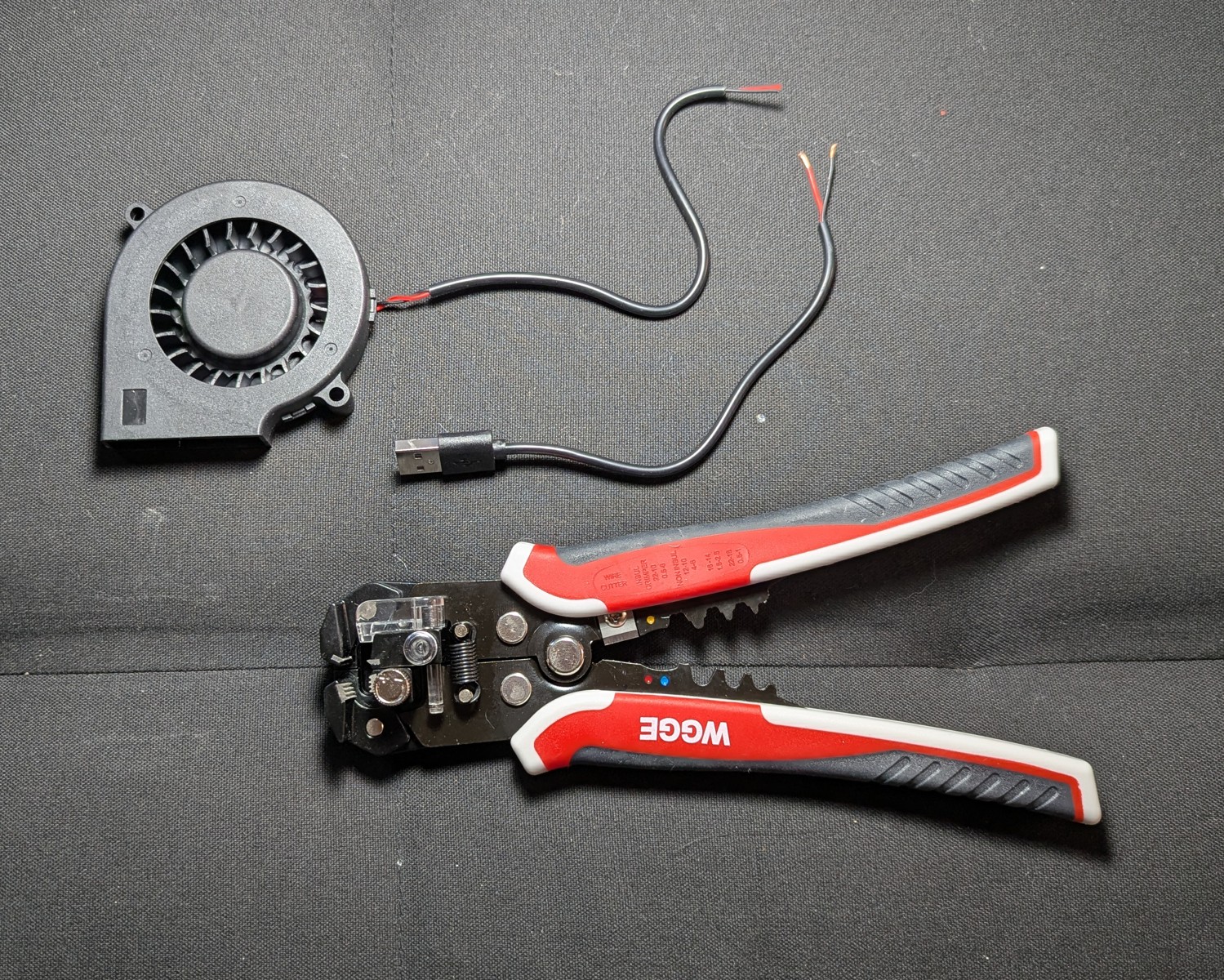
Cut the USB cable
Cut and strip the cable. Recommended slack: at least 75 mm (3 inches) on the blower side and USB side.
For the sheltered variation, this slack is needed so that the blower wire can reach the boost converter. (In the sheltered version, the boost converter is mounted to the hinge side of the unit.)
A “self adjusting automatic” wire stripper can save an enormous amount of time and heart break. Manual wire strippers are intended for use with sheathed wire, not USB cable, and it will damage the inner wires of the USB cable if you’re not careful.
A self-adjusting automatic, on the other hand, can strip the outer sheath of USB cable in seconds and leave inner wires intact. The self-adjusting automatic stripper can also strip gauges on the very small end.
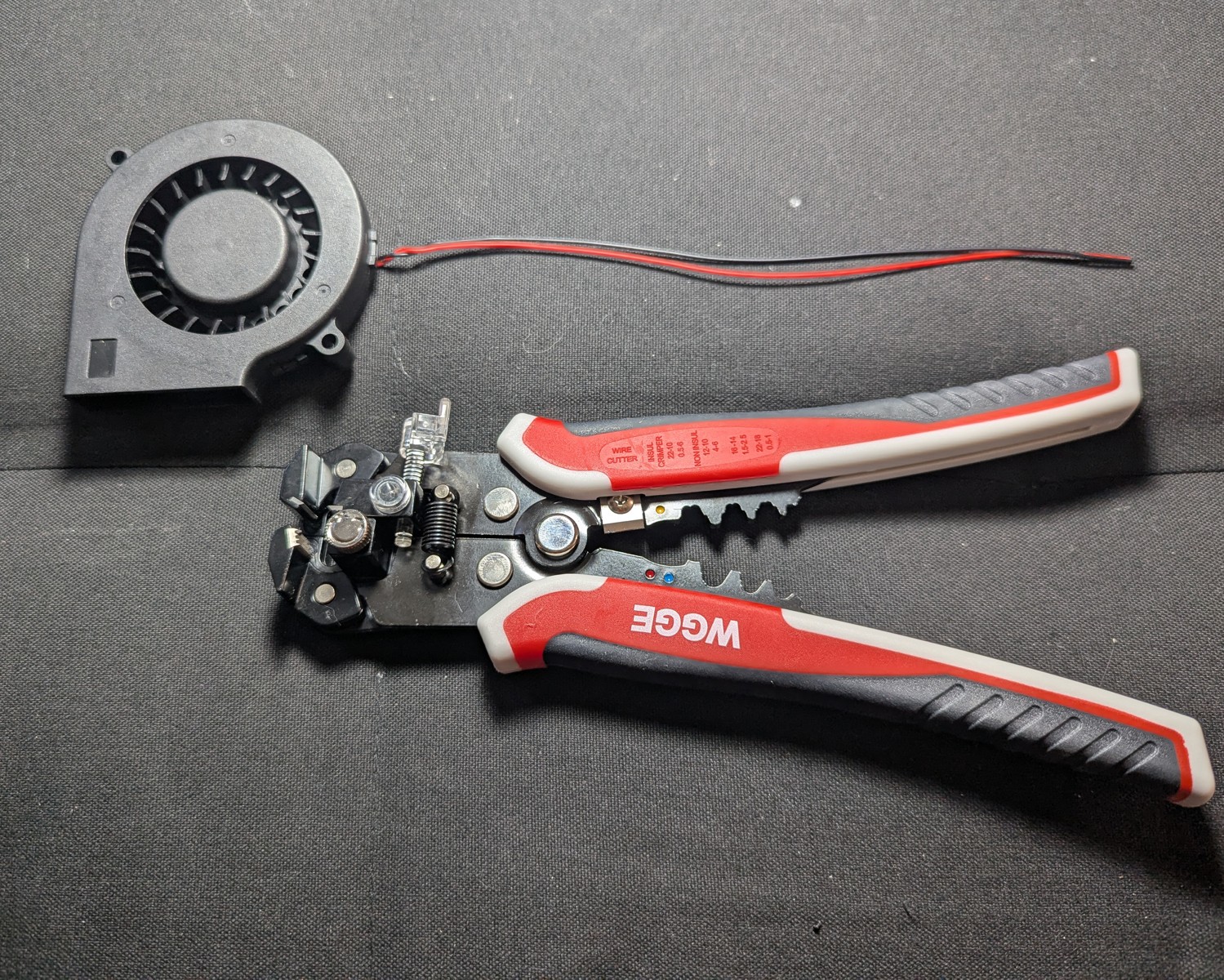
The above wire was stripped of its outer sheath in seconds using the auto wire cutter.
Test the blower again
This build uses a boost converter to maintain steady voltage with a small cost to battery life. This also makes the air flow adjustable for your needs, and ensures even airflow delivery throughout the charge cycle of the battery.
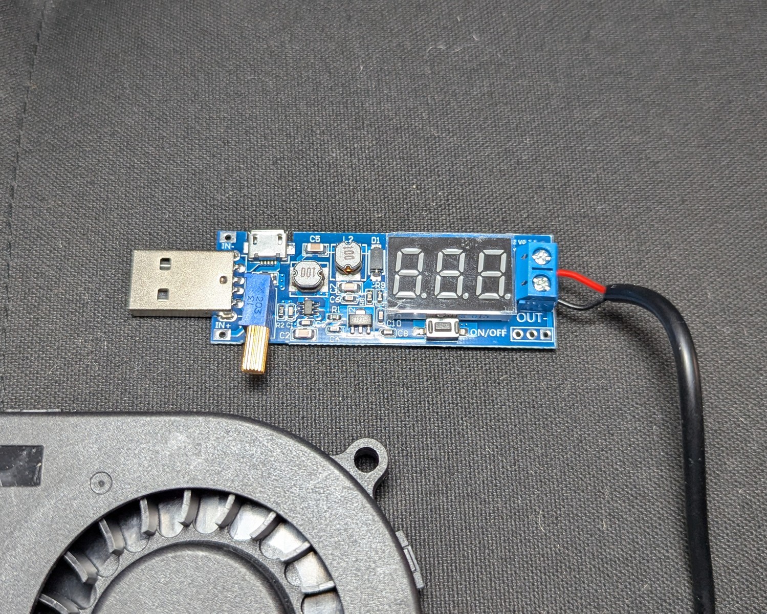
Without a boost converter, airflow can weaken as the battery loses charge.
5.3V Minimum recommended for good air flow and 8 hours of battery.
6V Maximum rated over-voltage for most 7515s. Higher protection, higher airflow, and about 6 hours of battery.
Attach the power source
The battery listed on the materials page is rated for 5V DC, 2.4 A, 5000 mah/18.5 Wh. This build has only been tested with this power rating. Use any other power rating at your own risk.
That said, one advantage of the boost converter is that you can use a wide variety of input voltages. There’s nothing theoretically wrong with using a battery with a different rating from above.
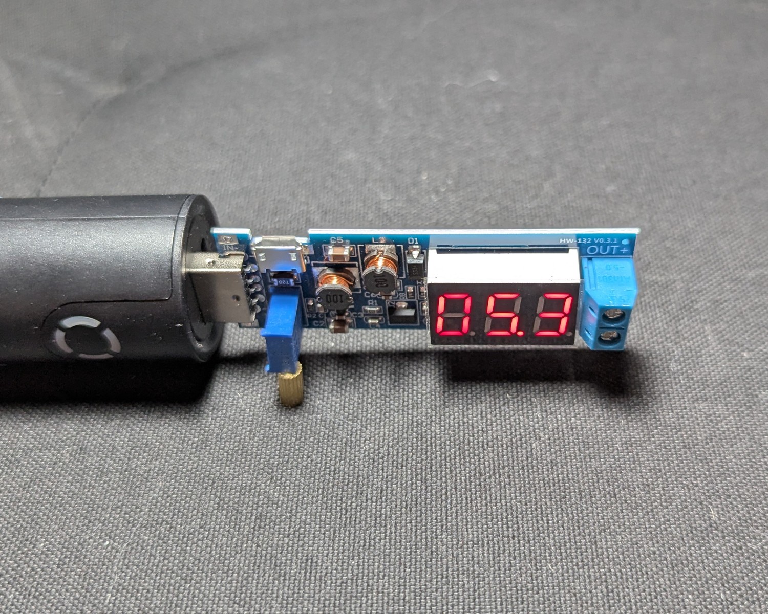
Attach the USB power source to the boost converter. Dial the boost converter to 5.3 V. Disconnect the battery.
Attach the blower to the circuit, using the screws, ensuring correct polarity. Red wires connect to terminal designated with a plus (+) sign, and black wires connect to terminal designated with a minus (-) sign.
Reconnect the battery.
Ensure that air is blowing
Adequate air flow is approximately 6 CFM.
Test for chatter
The shaft of the sleeve-bearing fan is supported by a thin oil film inside a porous bushing. That oil film is happiest when the load is steady and the shaft stays centered.
When you mount the fan vertically (shaft horizontal) and then move it sideways, a few things line up to make the rotor “snap” into a noisy state. Lubricating oil on the sleeve bearing catches and resonates, causing chatter. This is always present to some extent, but in some fan units, it’s particularly loud and annoying. It’s best to test this phenomenon before you proceed further with the project.
Test Steps:
With the battery connected, hold the blower upright and turn the body quickly left or right.
If the chatter is too loud, reserve the blower for use in another project and buy another blower, or go with a ball-bearing 7515 (with trade-off of a persistent high-pitched whine).
Make the blower enclosure
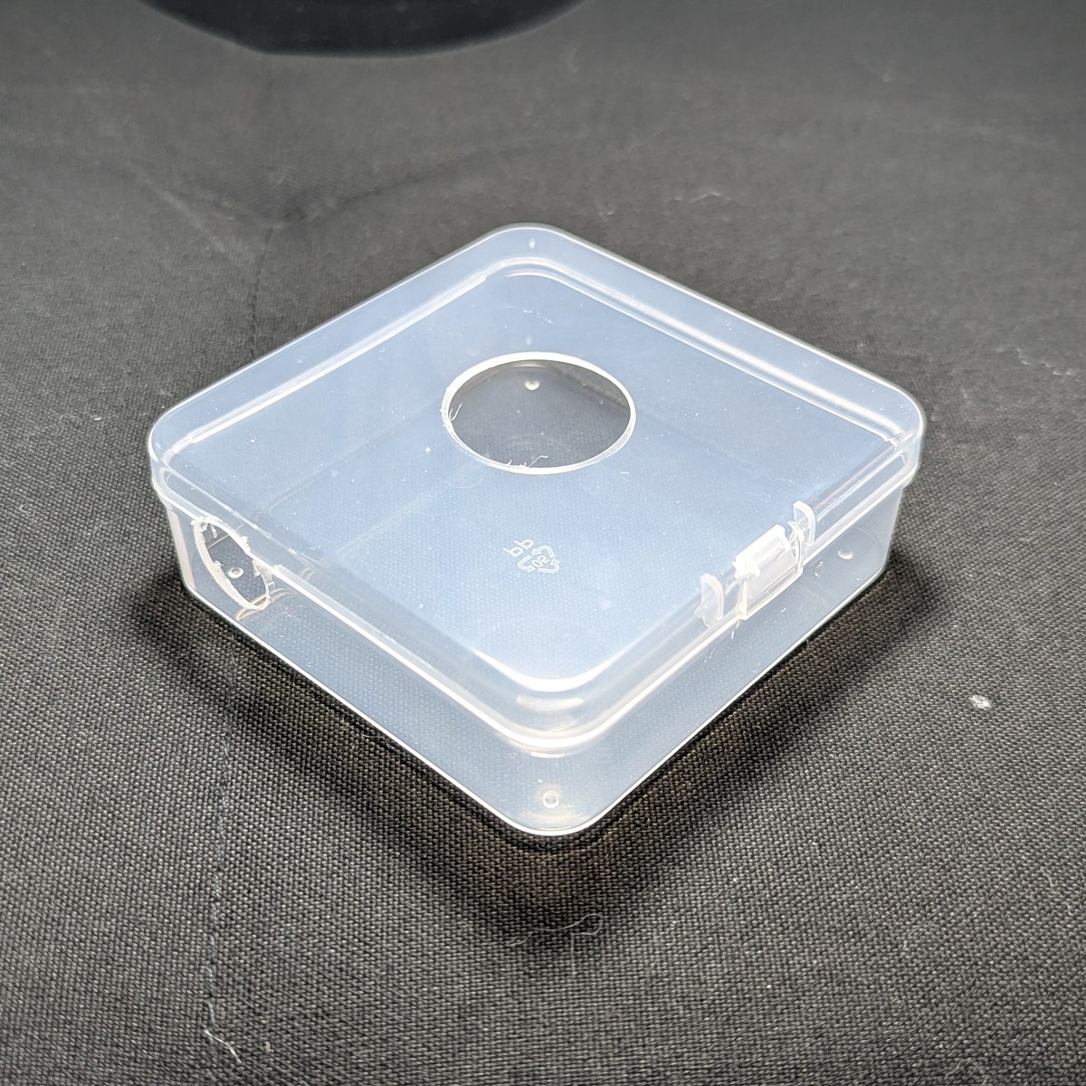
We’ll use an 85 x 85 x 30 mm polyethylene clear case for the enclosure, as they’re cheap, widely available, crack resistant, and easily drilled and worked. The drawback is that you can’t seal polyethylene with most types of glue. This will be addressed in the sealing step.
Clear polyethylene is also needed for you to inspect the adhesion of the blower enclosure’s components for bubbles and air leaks. That said, if you prefer an easier time sealing, then an ABS or polypropylene case is theoretically possible. (I couldn’t find one.)
The supplier of this clear case was chosen for quality, cost, and exact dimensions. Don’t deviate here, as all measurements are for this specific case from this specific supplier only.
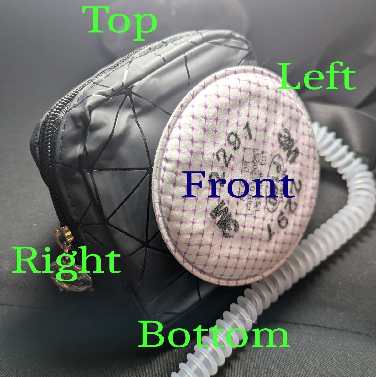
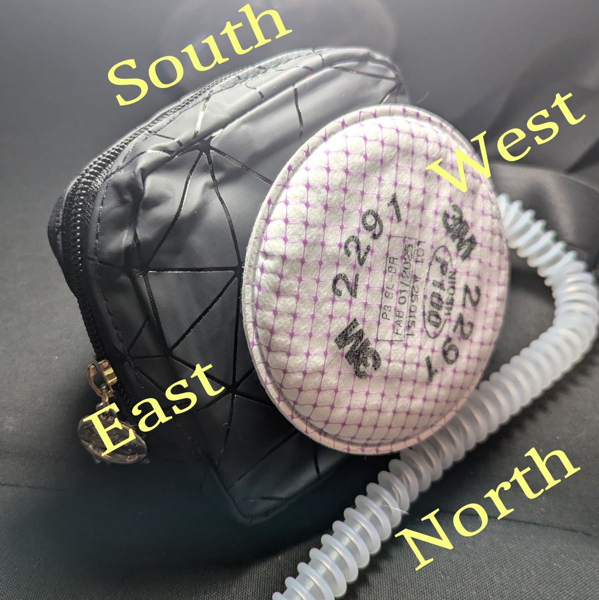
Orient the enclosure
Before we proceed, we need to establish a convention for referring to the sides of the unit.
Designate the side of the hinge on the clear case as North. The side with the clasp is South. The lid is “top” and the side at the bottom of the container is “bottom.” West and East must be inferred, but if you and the case are facing North, West is to your left and East is to your right.

Drill the ports
3 holes are needed:
Adapter port
- 26 mm diameter, centered on the lid.
- Drill using the step drill bit.
- Tip: alternate drilling from both inside and outside.
Hose port
- 15 mm diameter. Located west, 2 cm from north, centered between top and bottom.
- Drill using the step drill bit.
Wire port
- 2 mm diameter. Located at the bottom, centered between east and west, and about 3 mm from south.
The hose and adapter port are easily made using a step-drill bit. The holes can be marked with a scratch awl.
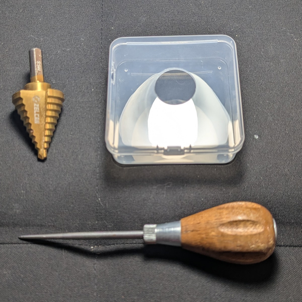
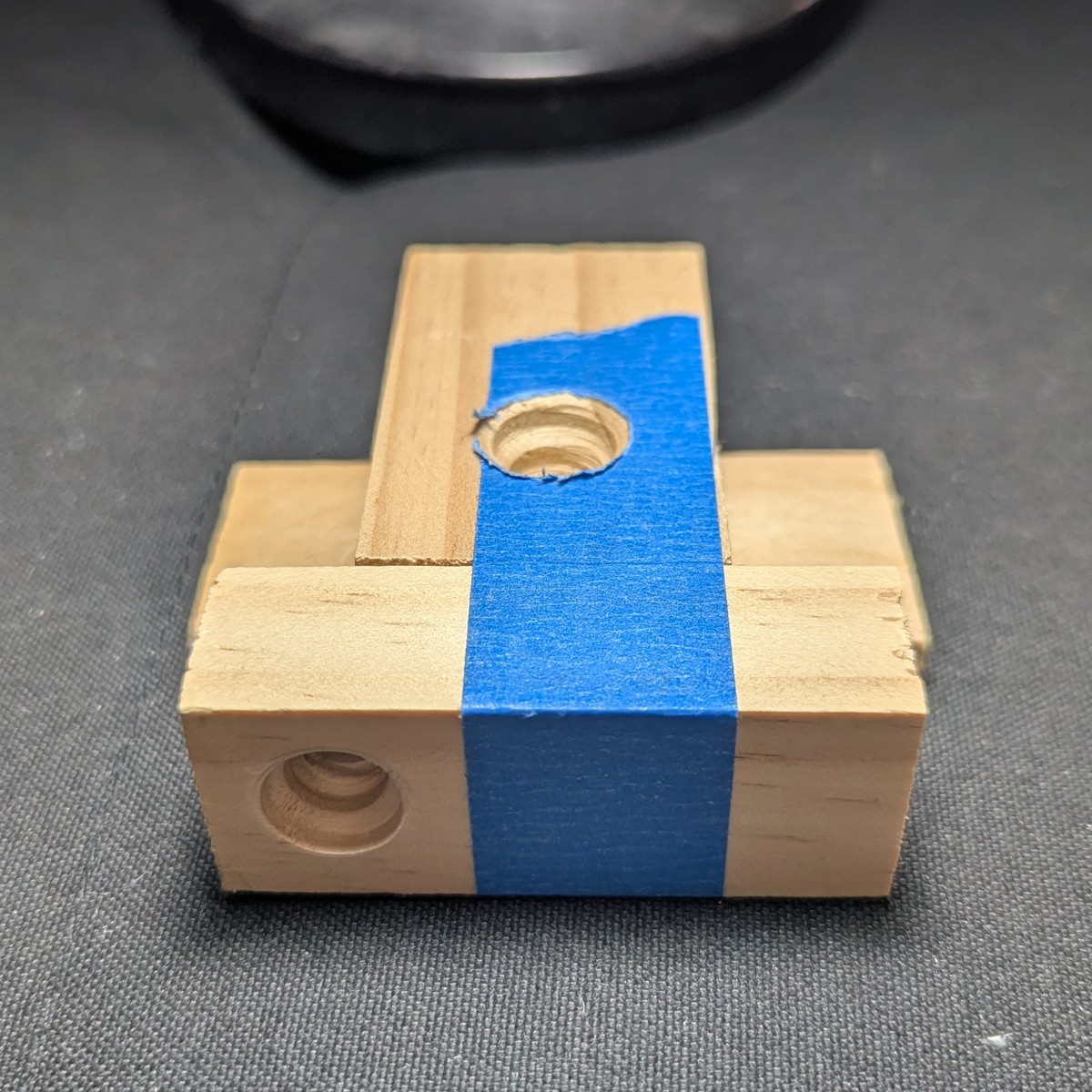
Tip: If you’ll be making many of these, then make and use a drill guide from spare wood.
Finished enclosure body:
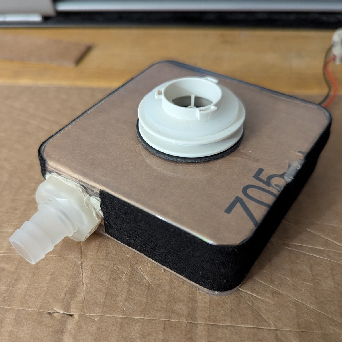
Attach the filter adapter
We have selected the Omnimask 3M filter adapter for its low profile and low cost. While official 3M adapters work, they cost more, protrude by an inch, and aren’t very fashionable.
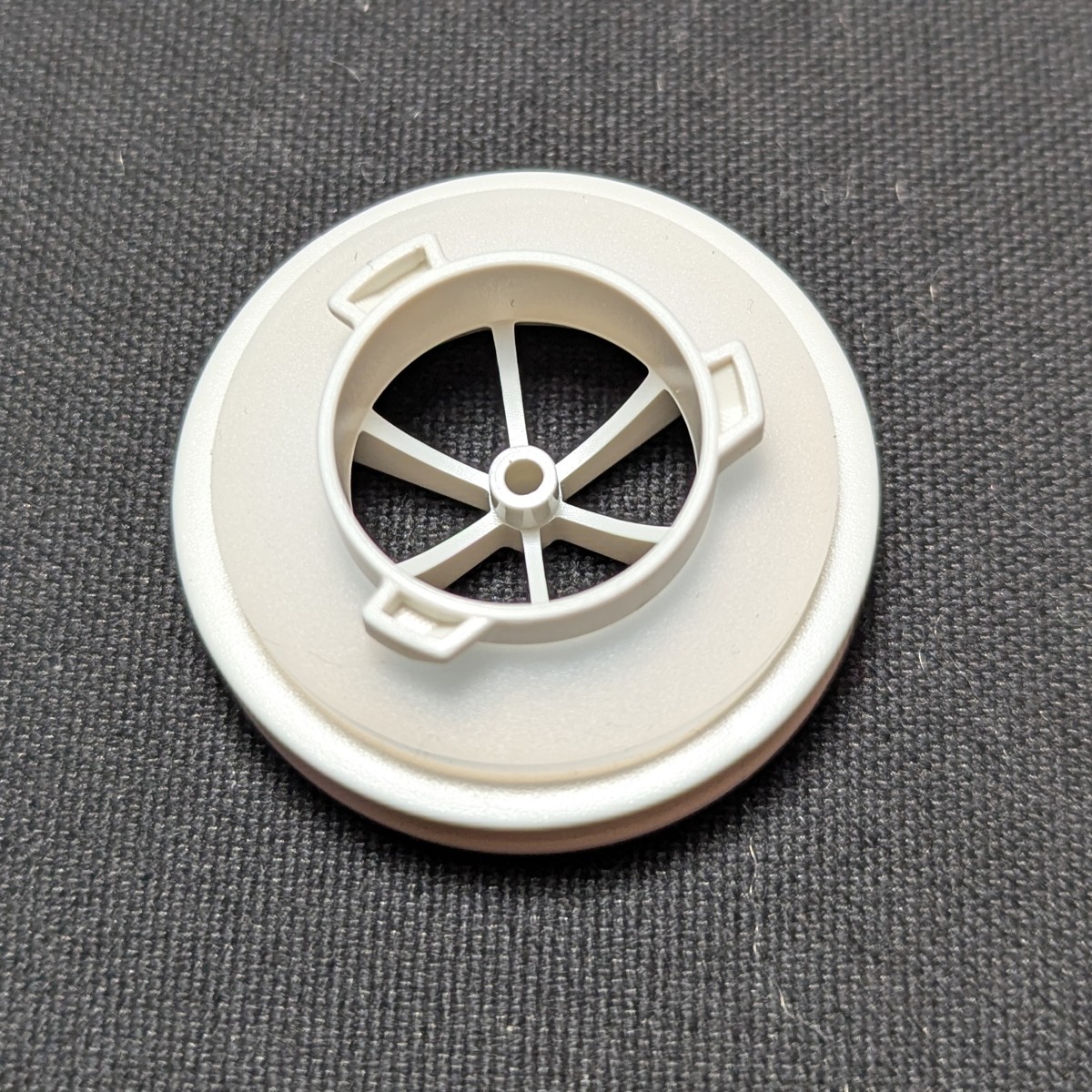
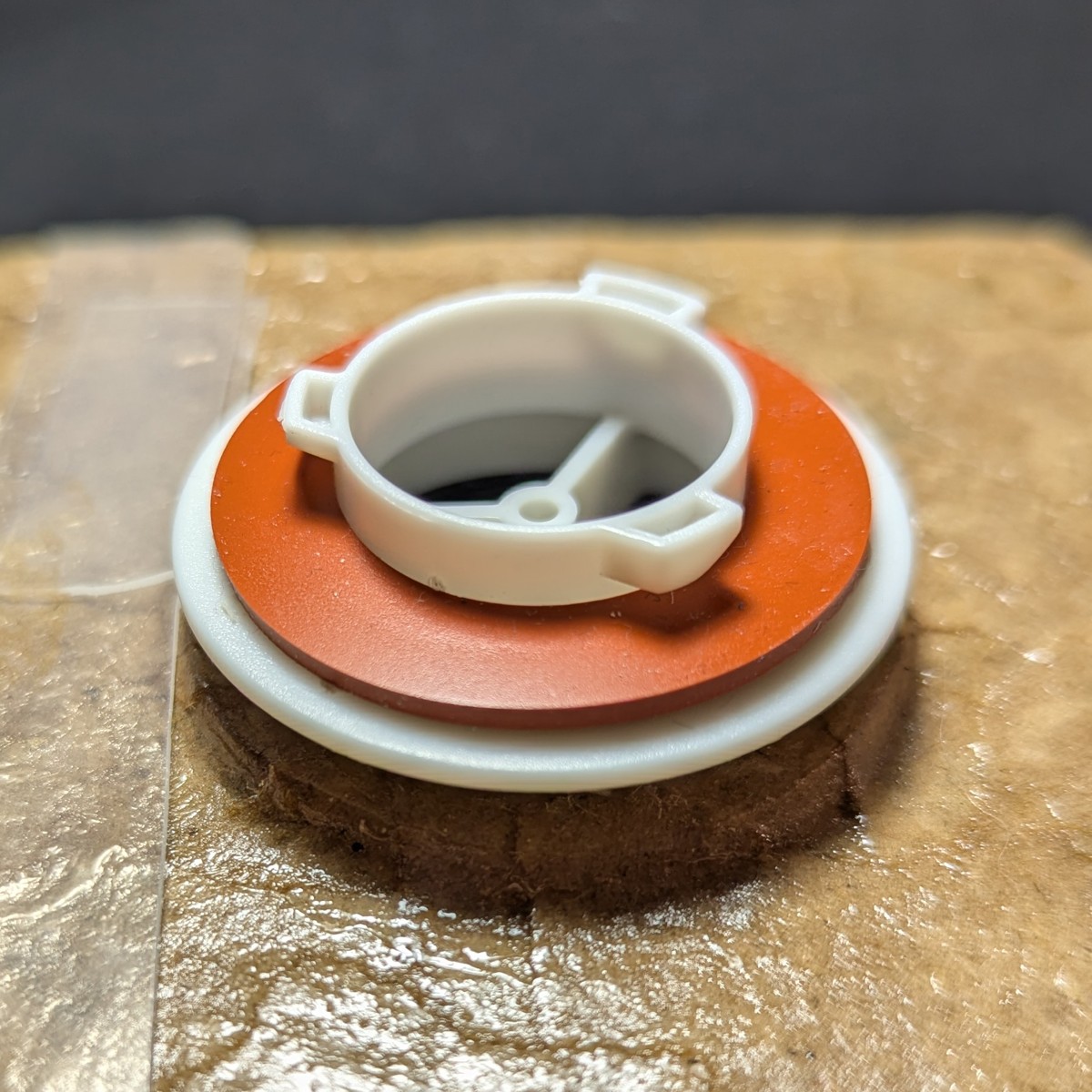
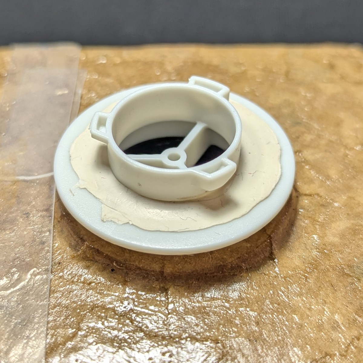
Repair the older Omnimask filter adapter
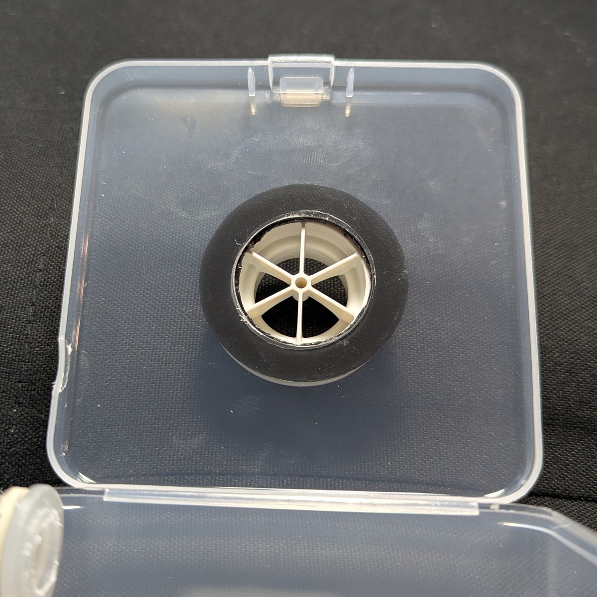
The older filter adapters have 3 spokes with an orange gasket. These have loose play on the bayonet connector column. Newer filter adapters (6 spokes with a clear gasket) do not have this problem.
To repair the older adapter, remove the gasket seal and put a ring of poster putty around the base. Install the gasket and connect a filter. This squeezes the putty to a thin layer that raises the gasket enough to restore the seal.
(Pictures are from an older build that uses paper mache for the sealing step.)
Cut an adhesive ring
Using a 3M double sided mounting pad (40 mm / 1.57 inch diameter), trace and cut a hole corresponding to the size of the enclosure’s adapter port.
Note
The red plastic backing requires extreme force to remove, which can warp the foam and cause installation failure. Instead of cutting a circular hole, leave a small inner tab that can be sacrificed in order to separate the red plastic backing.Orient the filter adapter
For aesthetic reasons, this step is recommended even if you intend to use this blower unit with the radially symmetric filters.
Orient the filter adapter by attaching it to a 3M 7093 filter. Align the filter how you would like. I suggest orienting the side that’s away from the filter’s attachment port to the west.
Install the filter adapter
Remove the paper backing and apply to the filter adapter.
Remove the red adhesive backing and apply to the adapter port of the enclosure.
If you left a sacrificial tab as suggested above, trim it off with some craft scissors.
Inspect the adhesion for air leaks. Be suspicious of air bubbles. If a path between the inner and outer edge of the ring is detected, you must start over. Because we are using polyethylene, do-overs are easy. Even the most tenacious mounting tape can be removed.
If you used the 7093 to orient the filter adapter, you may now detach it.
Working with poster putty
At several points in this build, thin and even strands of poster putty are needed. This can be achieved by twisting the putty between the thumb and index finger into a thicker, wobbly baguette of roughly 4 mm diameter, and then pulling both ends to the desired thickness. This aligns the polymer strands of the poster putty and results in a strong, thin strand of uniform thickness. This is especially important in the sealing step for the rim of the enclosure.
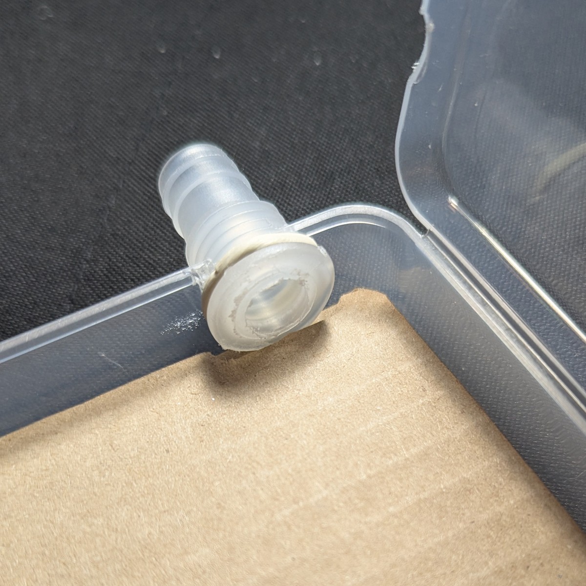
Attach the hose fitting
The hose fitting is sealed by poster putty. Stretch a 2 mm thick strand of poster putty around the outer flange of the hose fitting, and fit it into the western port with hand pressure.
Noise reduction
We will use layers of cardboard for stability and noise reduction. Cardboard reduces noise by directing sound waves into its corrugated channels, where waves cancel out. (Mufflers work on the same principle.) Layering the cardboard enhances this effect.
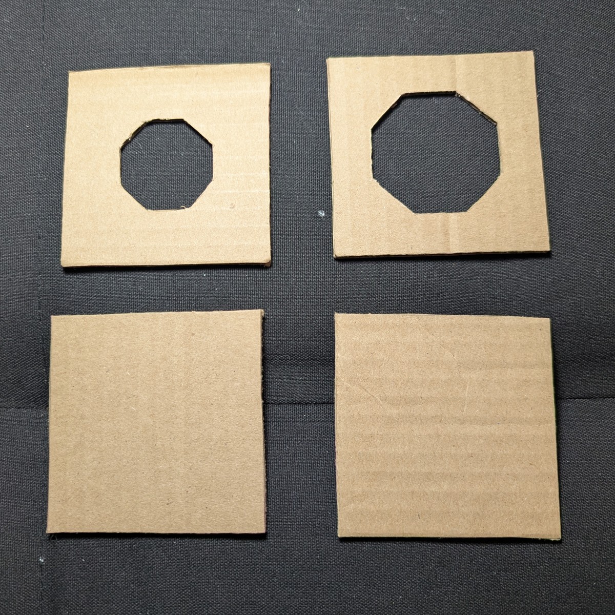
Cut the noise panels
Cut out four 78 mm squares of single layered cardboard. We use 78 mm to simplify the fitting on the lid, and to provide clearance from the hose port when the cardboard is fully inlaid.
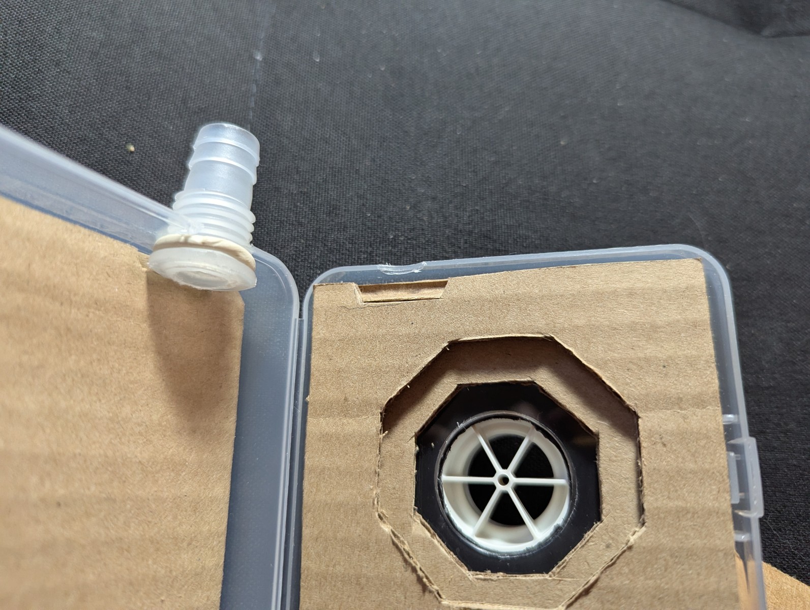
Of 4 squares, two require a centered hole for the filter adapter. The holes are graduated in size between the filter adapter port and the blower intake.
Recommended hole diameters:
- Inner lid noise panel: 48 mm
- Outer lid noise panel: 36 mm
From top to bottom:
- Outer lid noise panel
- Inner lid noise panel
- Inner bottom noise panel
- Outer bottom noise panel
Panels are layered with corrugations running orthogonally.
Smells
Place nothing inside the sealed unit that you would not be willing to smell for an extended period of time.Insert the noise panels
Insert the noise panels:
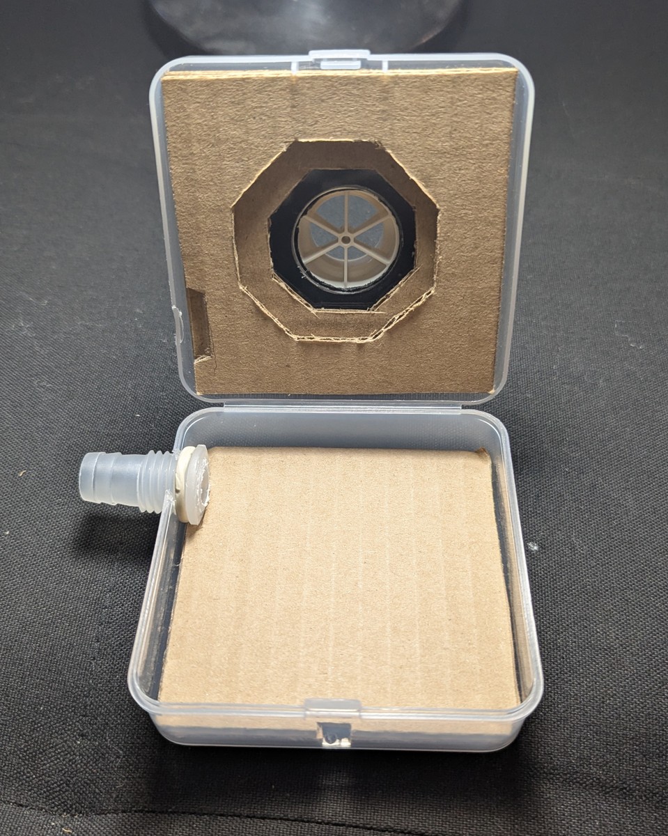
Divots have been cut out for the hose adapter base:
Additionally, cut out divots for the wire through-hole.
Install the blower
Thread the wire into the wire through-hole. Place the blower as shown and pack it with cardboard.
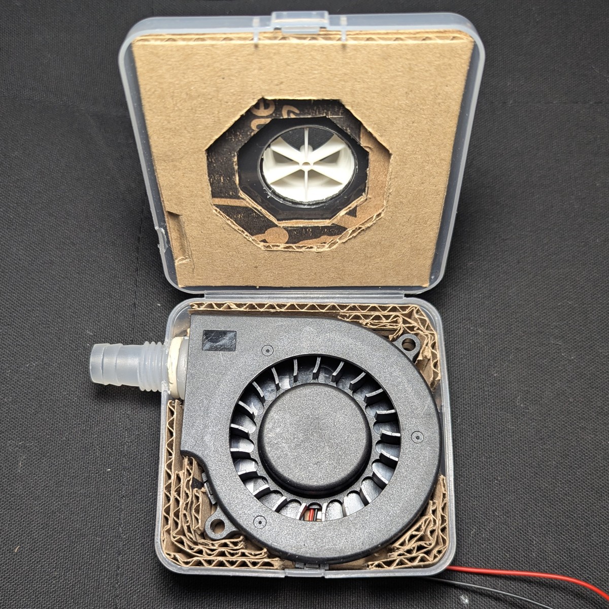
There should be some bulge on the sides due to the uncompressed ring of putty on the hose port.
Squeeze the east and west sides to check the amount of give. If there’s too much, support with more cardboard. We need to minimize give. Once the putty ring is compressed, this give will increase. Too much case flex may compromise the seal.
Close the enclosure
Close the enclosure.
Compress inner putty ring
Install the nut and use a wrench to turn the nut on the hose port. This creates pressure that squeezes out the inner poster putty to form a seal.
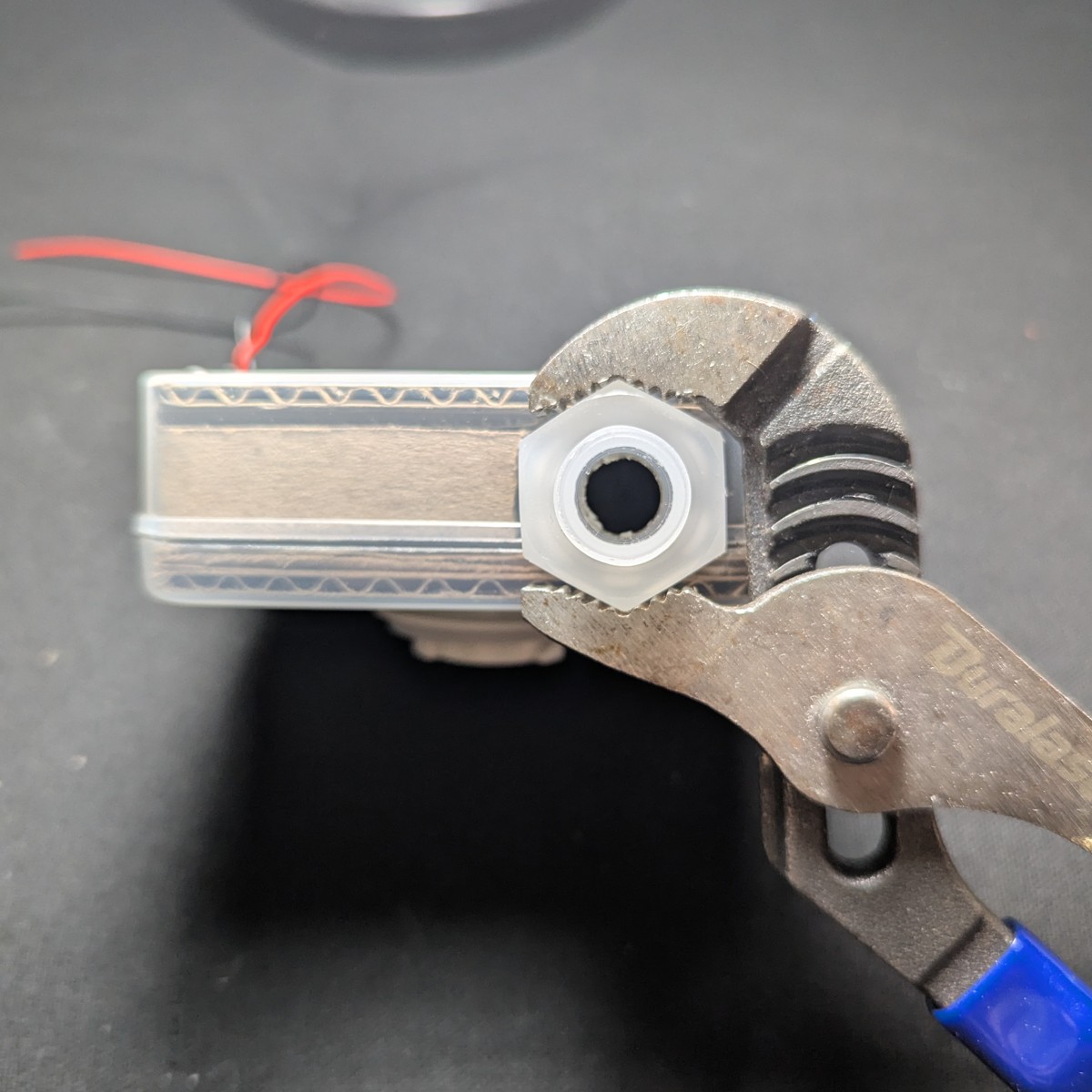
Unscrew the retaining nut and visually inspect for bubbles. Set the retaining nut aside.
Test for chatter again
Because of changes to the acoustic dynamics of the blower, an enclosed blower can surface issues with vibration.
Attach the boost converter circuit, and then attach the USB power bank. Check for chatter as per this section.
Seal the case
This is the most time consuming and difficult part of the build.
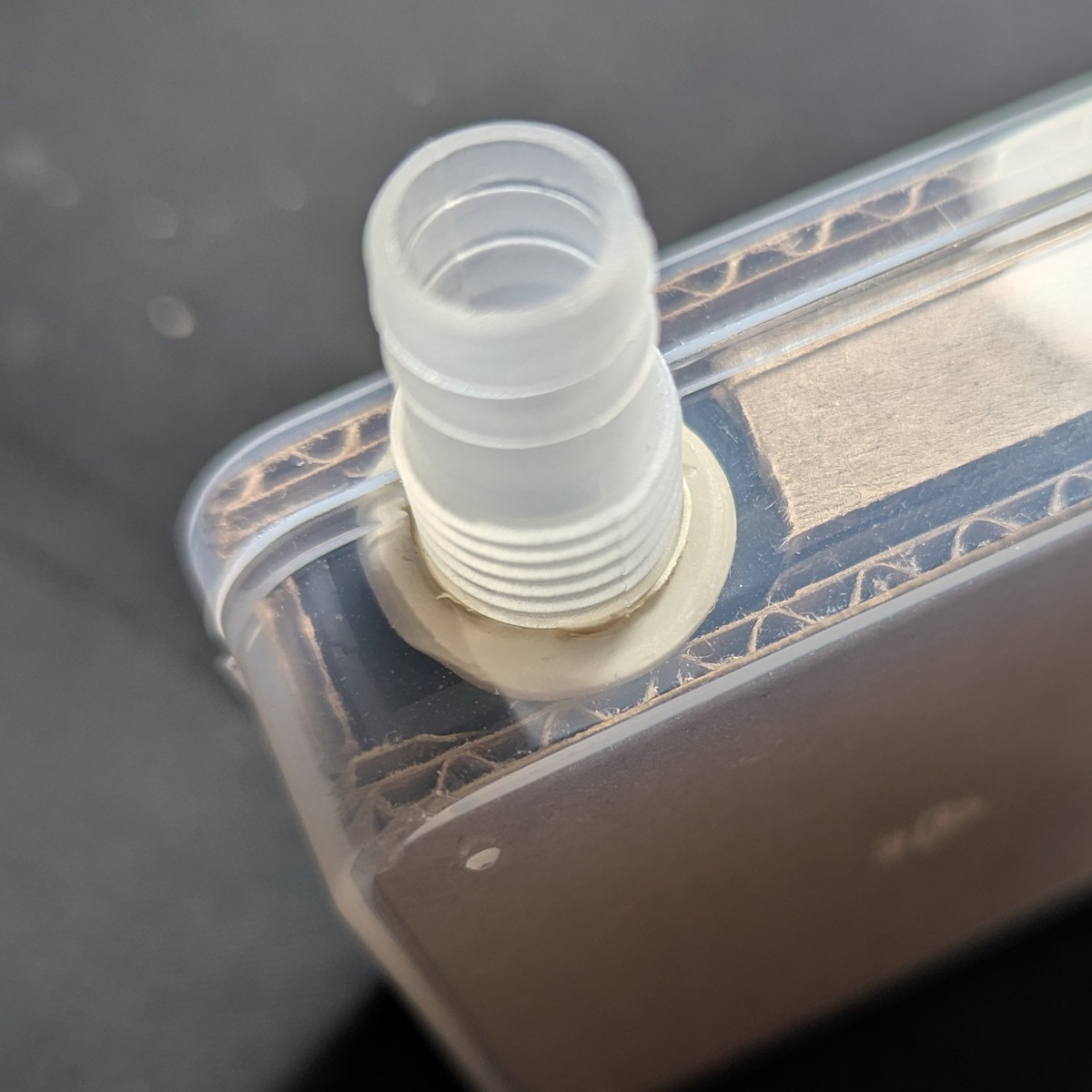
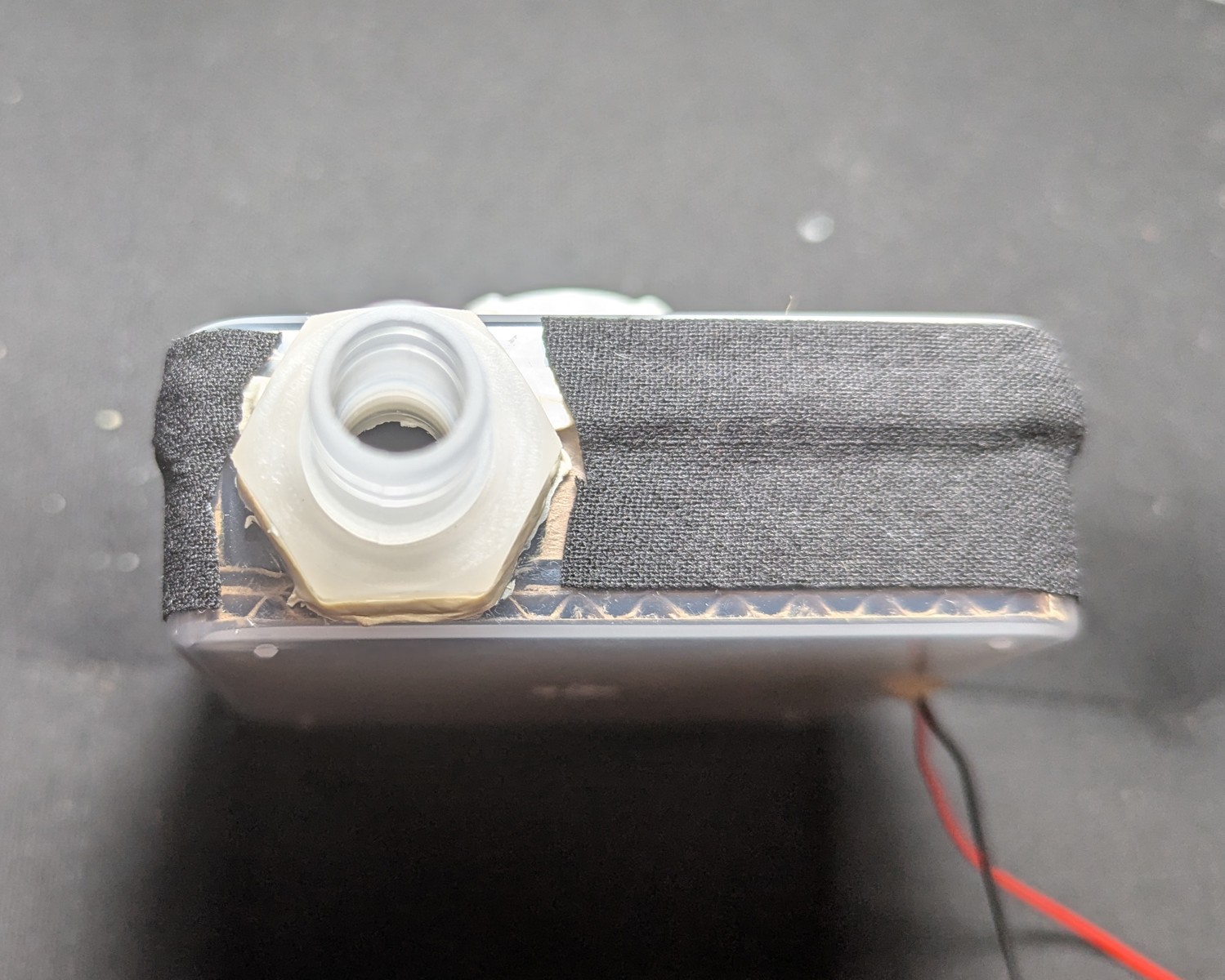
Seal the hose port
Lay a strand of poster putty at the base of the adapter hose thread.
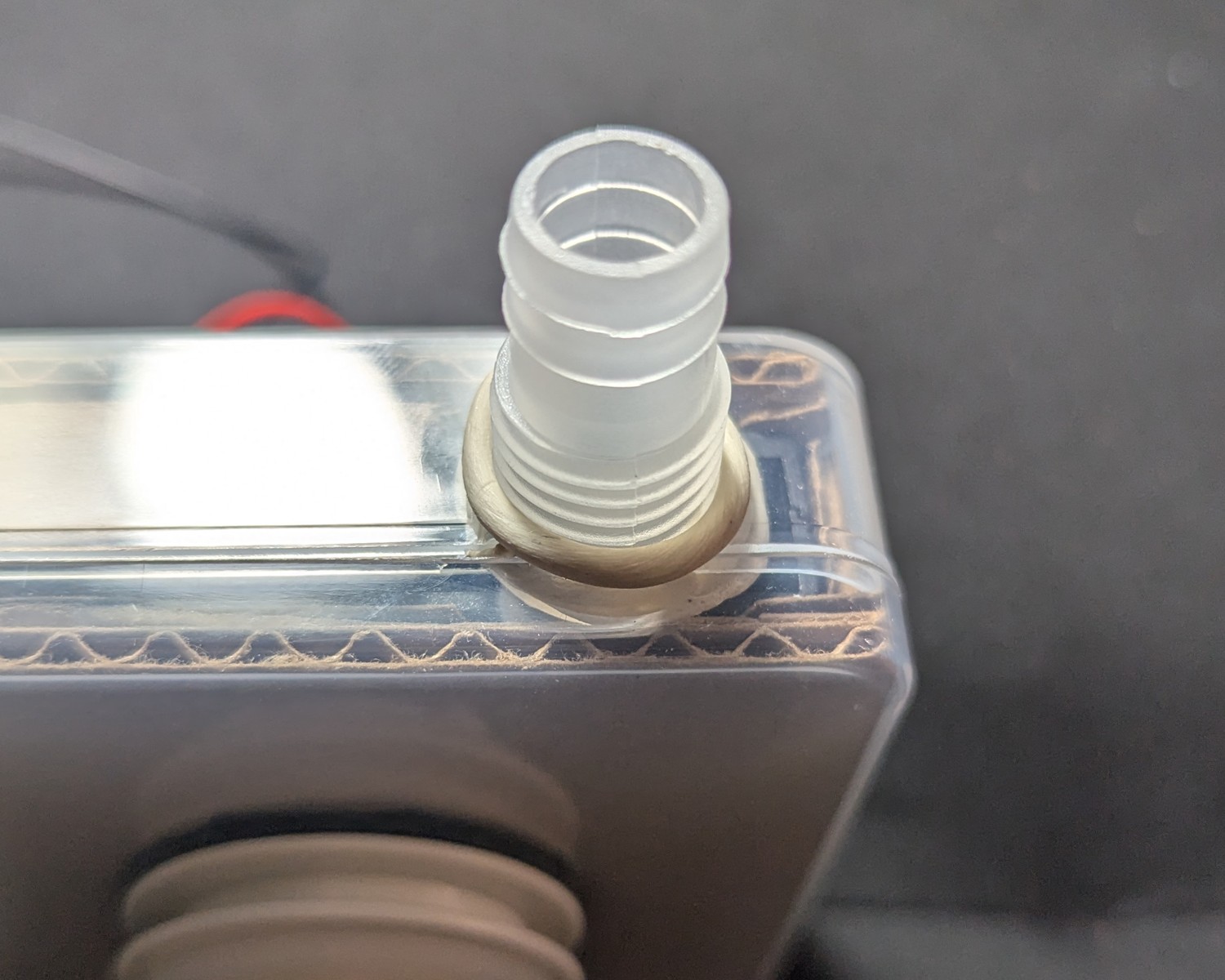
Screw the nut back in, applying torque, and squeezing the putty out to the sides. Don’t turn the nut all the way. If you do, it will shear the putty, compromising one level of the seal. Instead, turn until it’s about 2 mm from the west side.
Use the scratch awl or a toothpick to pack in the space with poster putty until flush with the edges of the nut.
Seal the lid
The clear case uses polyethylene. Glue will NOT stick to the case, and will peel when flexed. This includes super glue like cyanoacrylate.
Instead, we will seal with poster putty, and then put a barrier around the poster putty to protect it.
Lay a strand of poster putty around the seam where the lid meets the container. Remember, poster putty can be stretched thin by kneading in a twisting motion, and then pulling apart. For tips, check this section.
Press the putty into place.
Seal the putty
What makes poster putty so good at sealing polyethylene also makes it fragile for everyday wear and tear. We’ll be sealing the poster putty to harden it from the outside.
We can do so in a way that introduces a second level of air seal.
Cloth tape was chosen for its ability to conform to the geometry of the object it’s taping. The tape must hug the poster putty without introducing bubbles or air channels (after the tape is sealed).
By contrast, non-woven tape such as PVC tape and polyurethane have been tried, and these introduce air channels which drop the filtration efficiency of the unit significantly, so their function as a secondary seal is not fulfilled.
Seal the wire through-hole
Use poster putty to seal the wire through-hole.
Two strands are needed: around both wires, and between the wires.
Press it down into place.
Using a toothpick or scratch awl, apply pressure until the putty goes through the wire port and is visible on the inside of the enclosure.
Measure and cut a strap of cloth tape
Tape all the way around the putty. The adhesive adheres strongly to the putty, and this part can’t be undone. The tape adheres weakly to the polyethylene but the edges will be distant from the seam, ensuring a good seal.
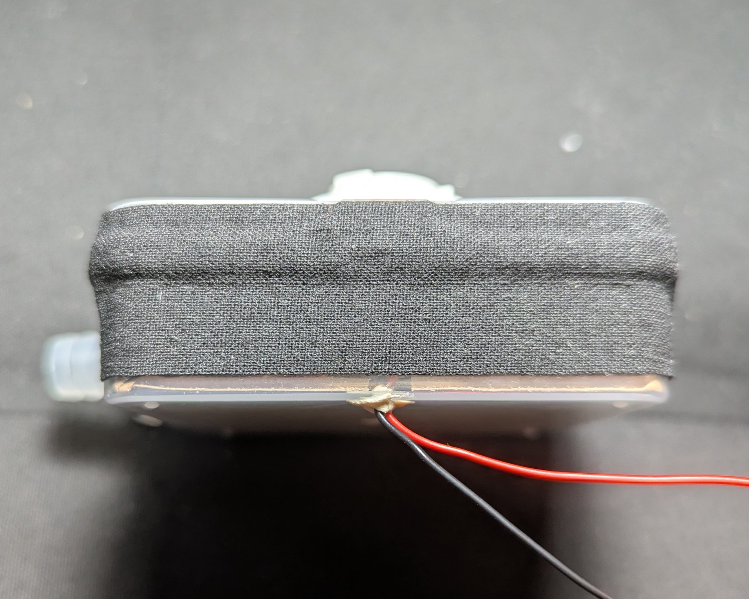
Note how the tape hugs the geometry of the putty seal.
Reinforce and waterproof the tape using wood glue. This also waterproofs the seal.
Wood glue was chosen for its combination of being waterproof, easy to work with, strong, and fairly cheap and easy to obtain. (As with most PVA glues, check your sensitivity. One alternative is to seal with shellac, which the cloth tape will wick just fine.) This also prevents the seepage of adhesive over time, as the blower should be useful in all weather conditions.
Brush the glue onto the tape. Make sure to get the edges. A disposable nail polish brush can be used.
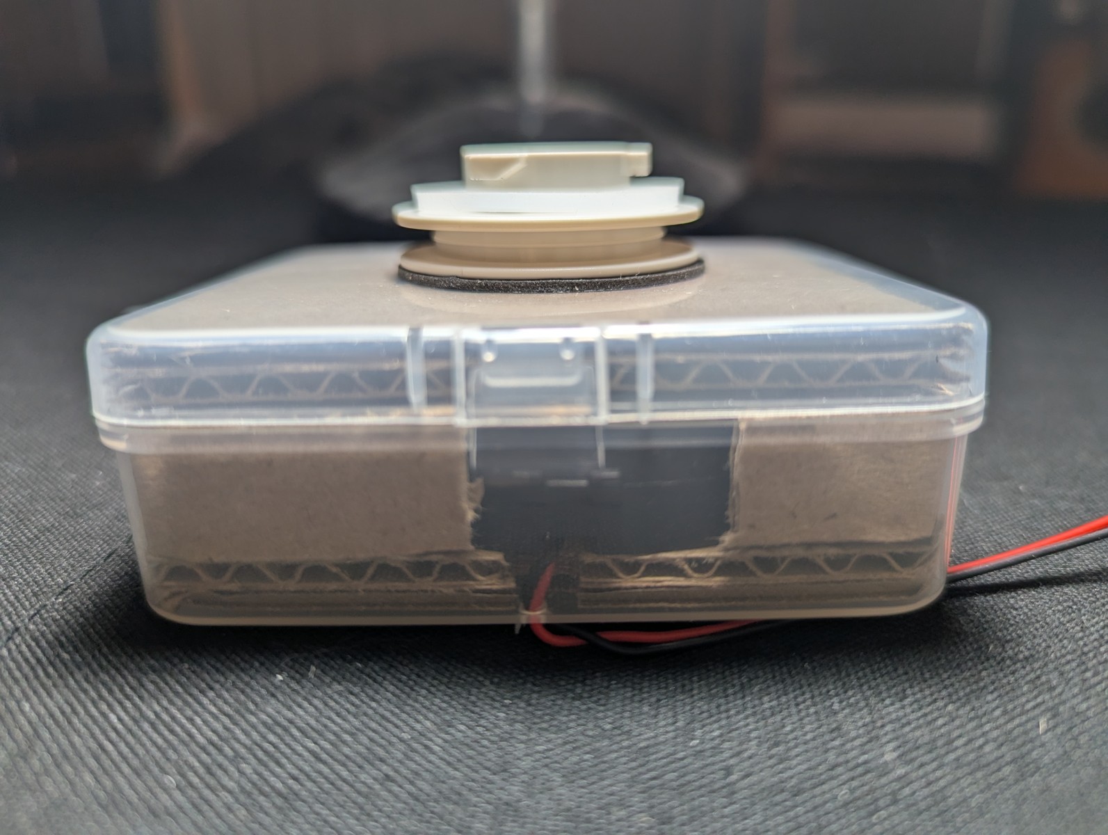
Here’s the finished unit that goes into the case
Optional: paper mache
If you can devote an entire day to the sealing step, you can opt to use Paper Mache.
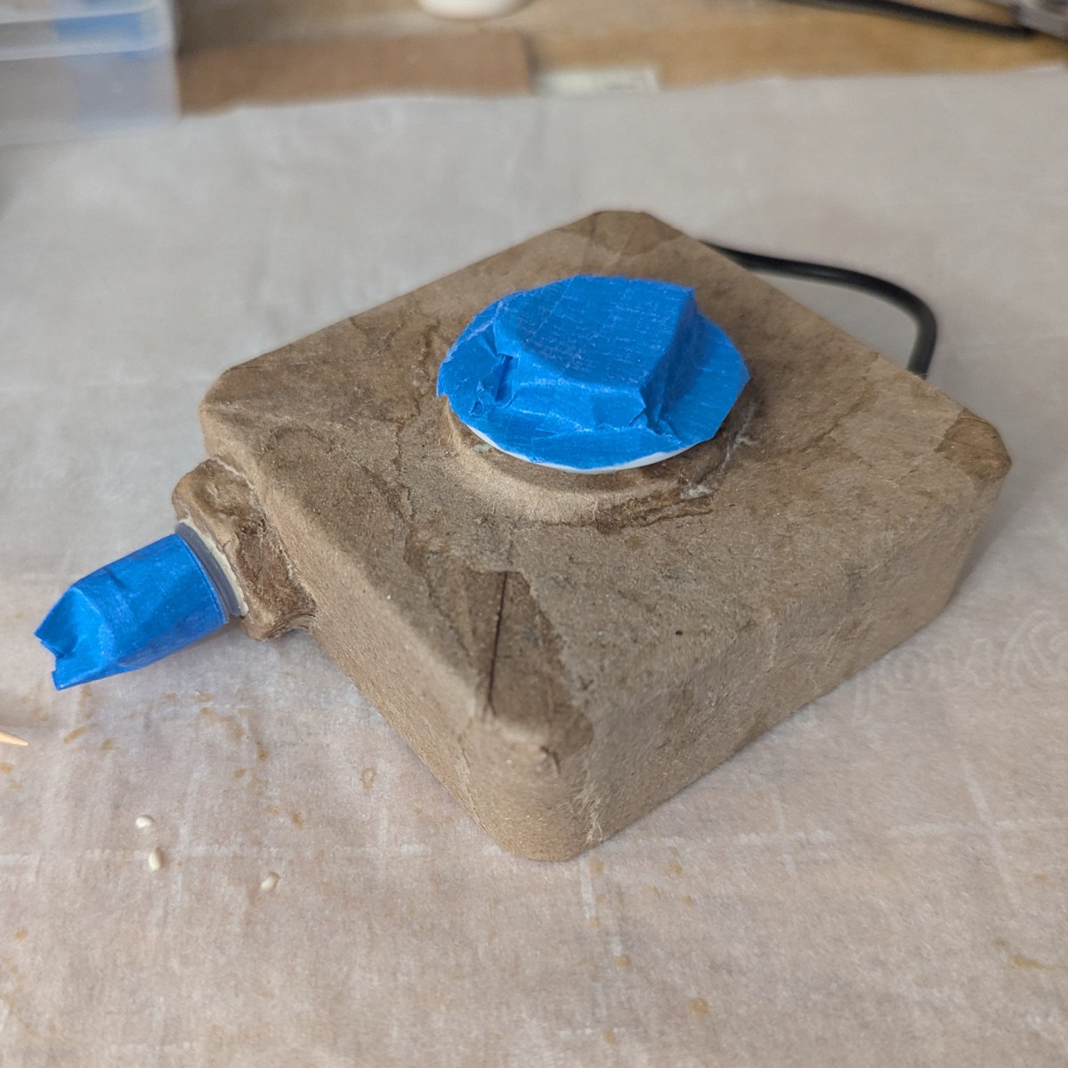
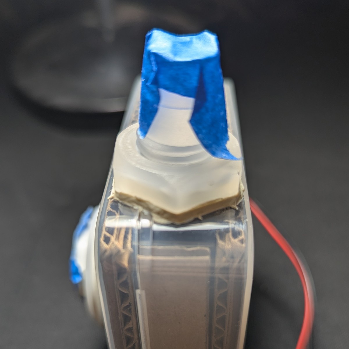
Tape the lid closed using masking tape.
The masking tape will help the paper mache grip the polyethylene.
Make a paper mache paste from dilute wood glue (about 3:1 glue to water).
Tear off small bits of paper and seal the enclosure.
Test the seal
Connect the hose and attach a filter.
Connect the boost converter. Connect the battery.
Connect the sample tube, and disconnect the ambient air tube. This causes the fit score to be calculated with respect to the position of the ambient intake port, not the ambient tube. Next, place the filter as close to the ambient intake as possible. This will give a more accurate measure of the nominal filtration efficiency, or fit score.
Run a single exercise, ensuring ambient particles are above 2000 per cubic milliliter.
The nominal filtration efficiency with 3M 2091 filters should be on the order of 100,000 to 999,000. If it’s less, there may be a leak.
Troubleshooting a low FF can be difficult. The most common source of leaks is forgetting to seal the wire through-hole, since it’s tiny and on the underside of the blower enclosure. Furthermore, check that you have a functioning filter adapter, and that you haven’t missed any of the sealing steps.
Make the carrying case
A carrying case is needed to mount the blower unit to you and hold the battery.
The carrying case should be lightweight, weather resistant, and adjustable.
Only instructions for the exposed variant are provided. For the sheltered variant, you may look at the pictures and infer the proper construction.
Orient the case
We have to name the sides so that the zipper pull closes to the righthand side, away from the hose.
Point the side with the zipper up. This is the top. The opposite side is the bottom.
Zip the zipper all the way closed. The side with the zipper pull in the closed position is the right.
The opposite side where the zipper started is the left.
Orient the case so that the left and right correspond to your left and right.
The side away is the front. The side nearest is the back. This is important: the front of the case is where the filter attaches, and in the exposed variant, it will face away from you.
Orient the blower enclosure to the case
Line up the blower unit with the case so that the blower unit’s north side (as per the enclosure orientation) faces the case’s bottom, ensuring that the zipper pull in the closed zipper position is on the right side, with “bottom” and “right” defined above.
The case and unit properly oriented:
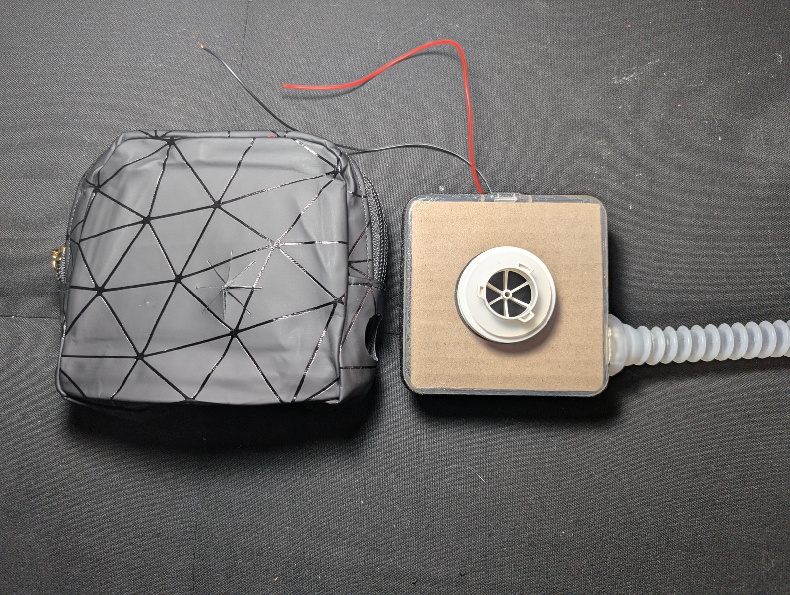
This will be the ironclad orientation for the blower unit with respect to the case, for the rest of this build.
Warning
Follow the above instruction carefully. If you get the orientation wrong, then the zipper pull will be on the WRONG side. This will make it difficult to quickly check the battery level and remove the battery for charging.Cut the port holes
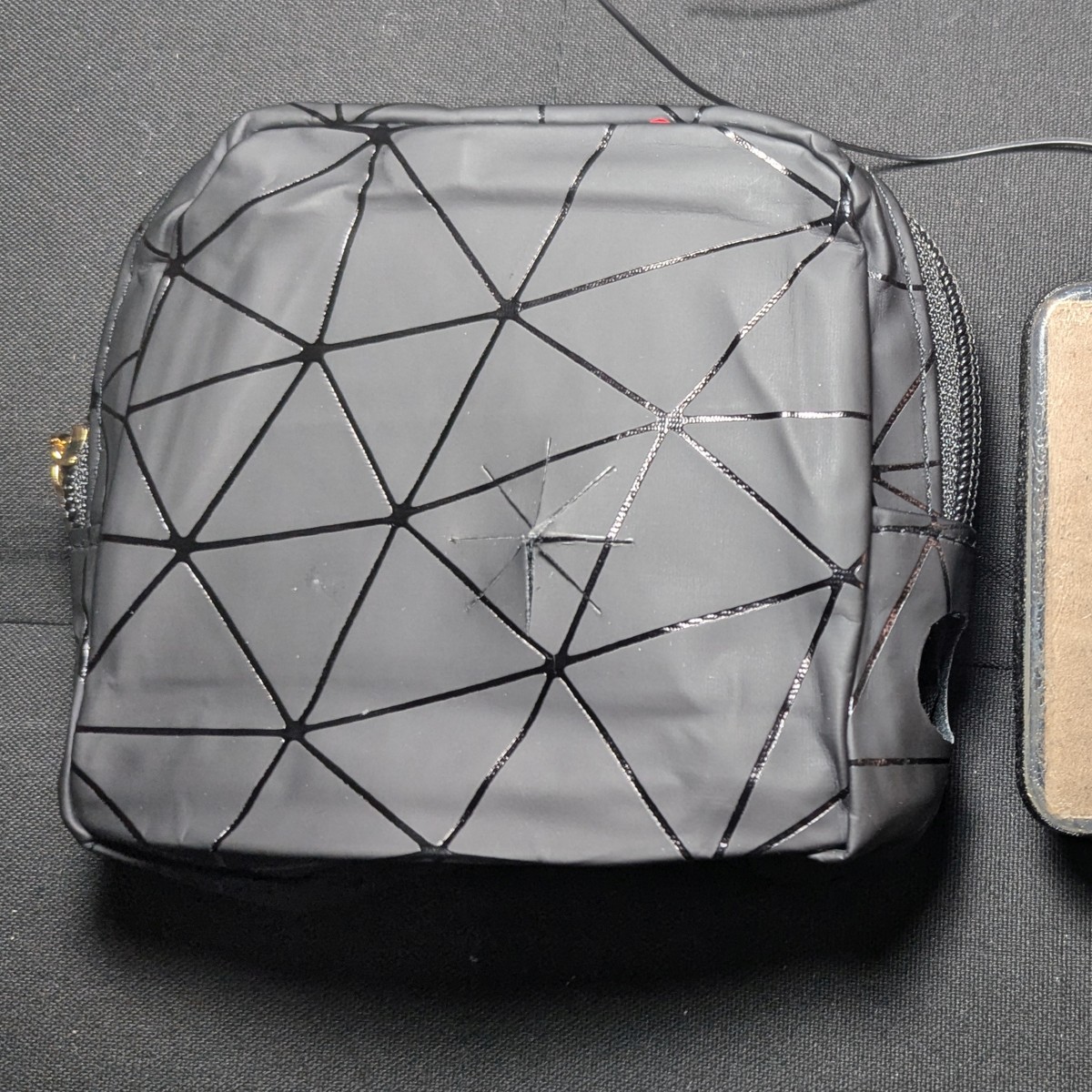
Insert the blower unit with the proper orientation, and press it against the case left. Mark the center where the hose port presses against the case left. Use this mark to cut a 20 mm hole for the hose port.
Once cut, insert the hose port, and mark the center for the adapter port. Cut an 8-point star shape that is 30 mm wide, so that the adapter port fits snugly.
Attach the strap
On the back at the top of the case, mount the strap on the left and right side.
Options for mounting the straps:
- Punch 4 holes and grommets, and thread the strap loops through.
- Sew a set of D-rings and thread the strap loops through.
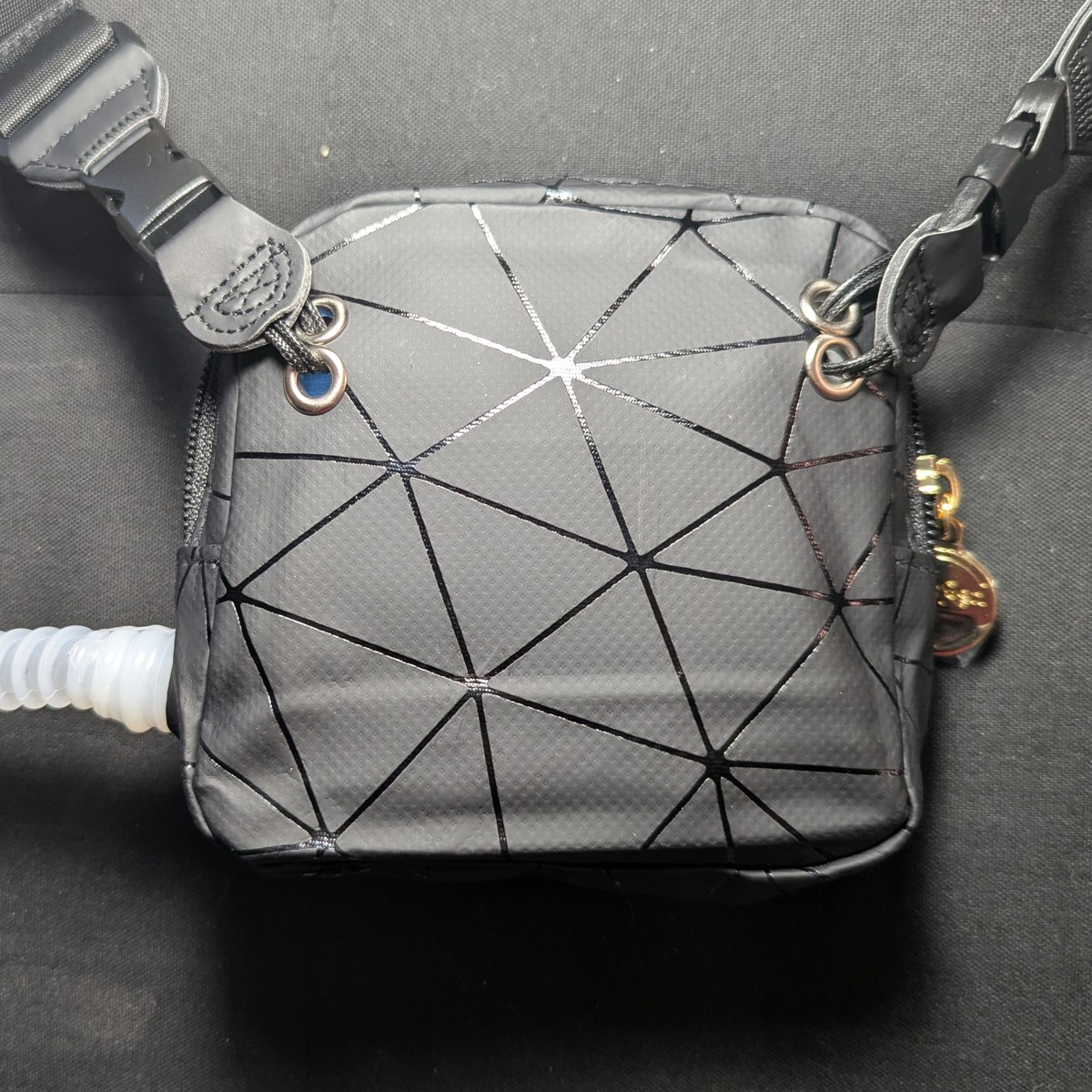
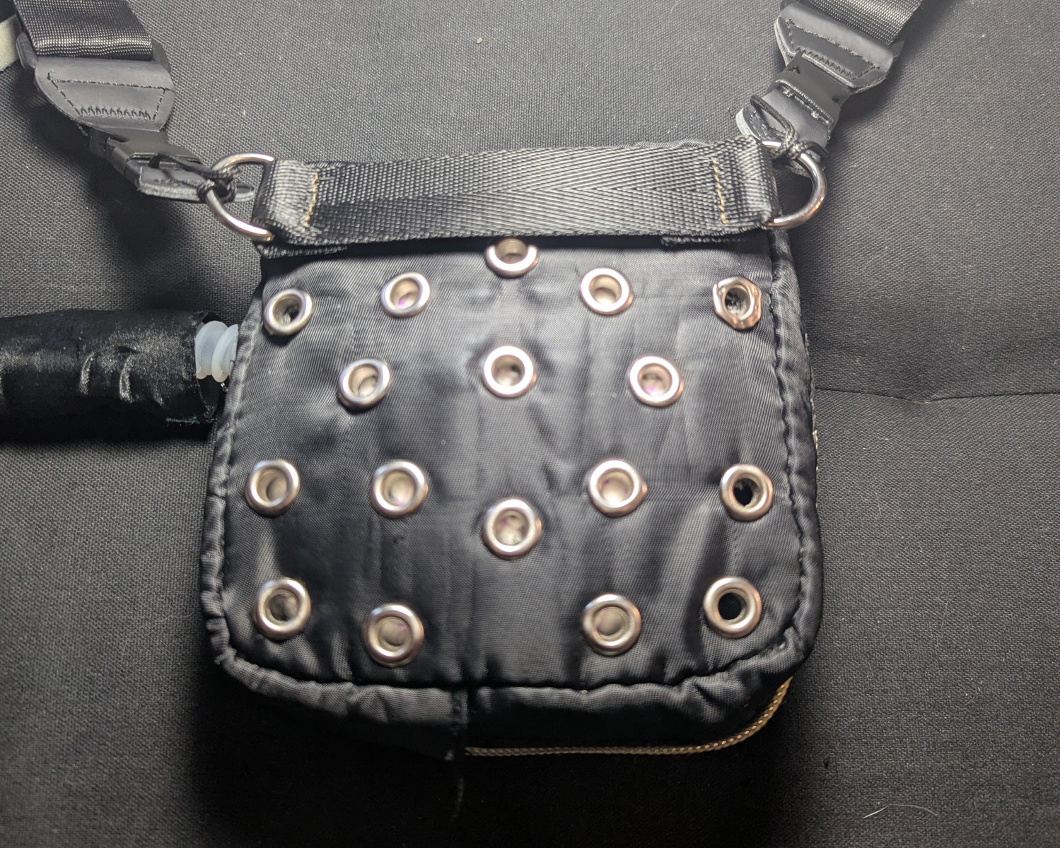
The above also shows the back of the sheltered case variant. Note the grommet holes for airflow.
Use any adjustable strap that you like. A cheap one is suggested on the Materials Page.
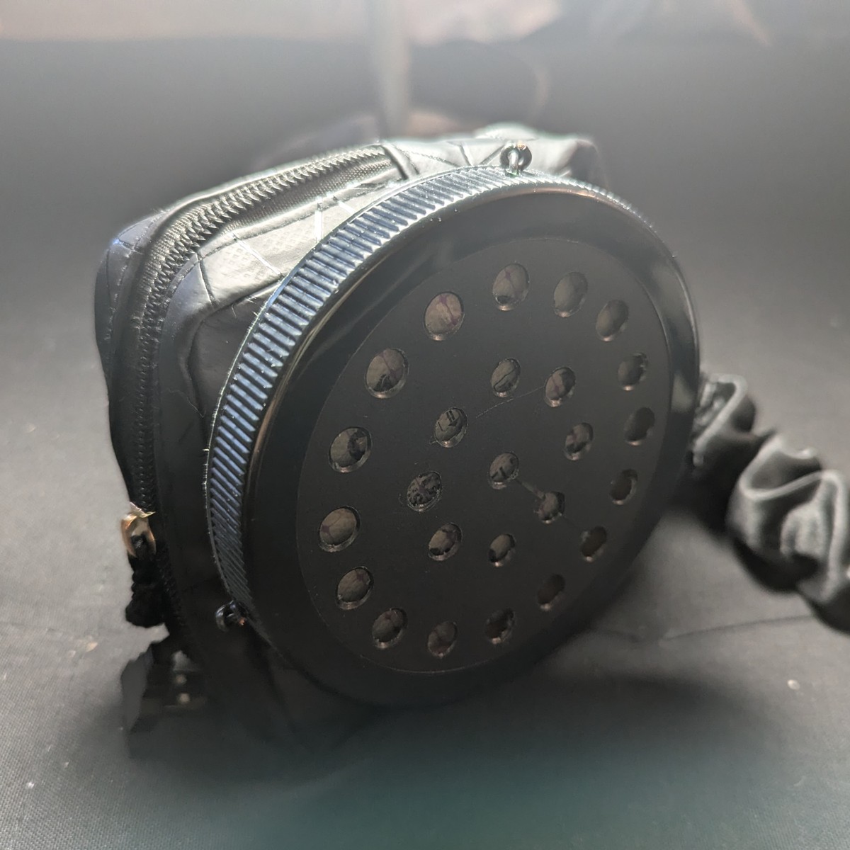
Make the filter cover
This is optional.
This filter cover allows you to wipe down the surface for safe handling. Be advised that alcohol vapors may compromise filtration media.
You can also paint the filter cover for aesthetics.
The filter cover is not waterproof.
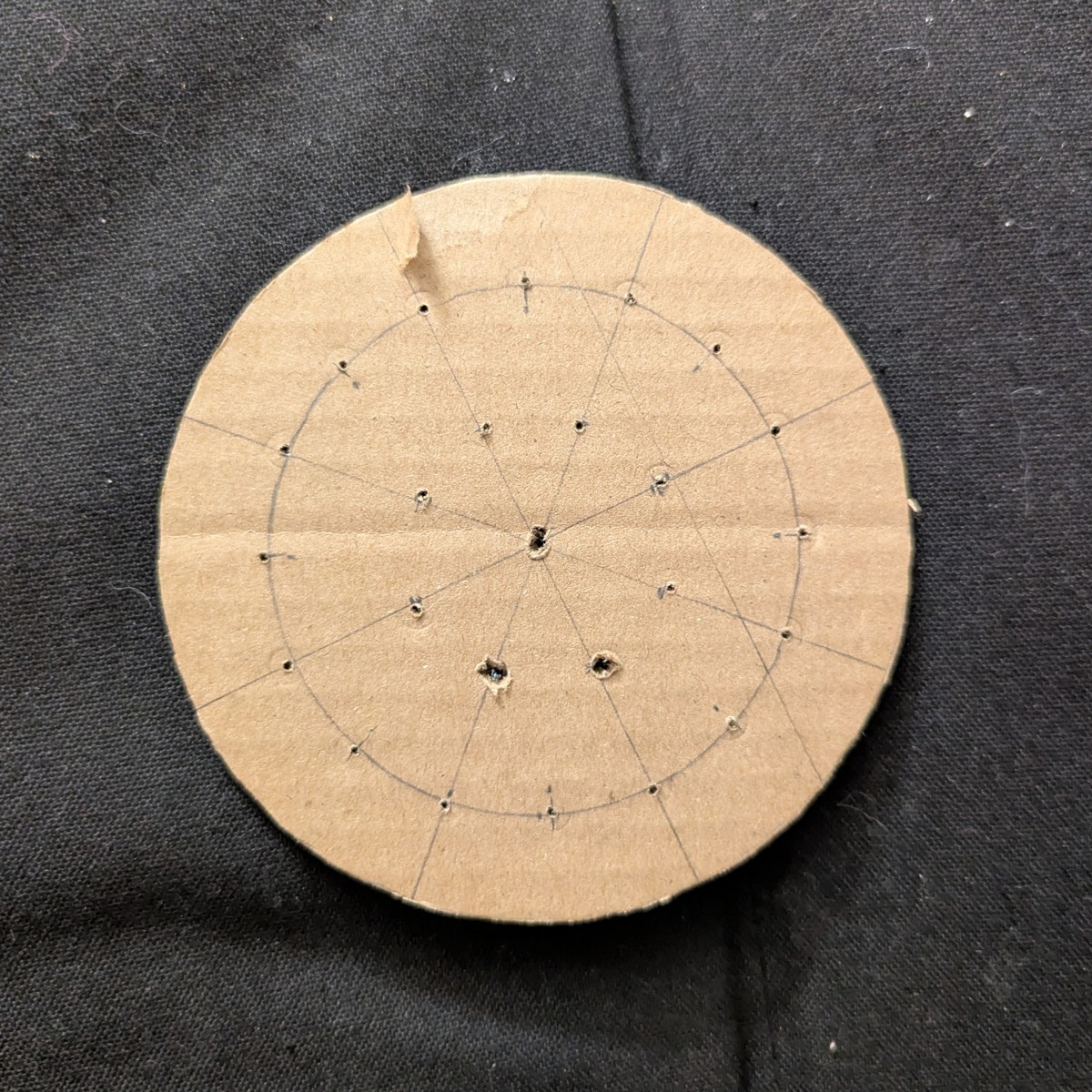
Make the stencil
Draw and cut a circular stencil.
Stencil measurements
| # Holes | Radius | |
|---|---|---|
| Center | 1 | 0 mm |
| 1st Ring | 8 | 18 mm |
| 2nd Ring | 16 | 38 mm |
| Perimeter | 54 mm |
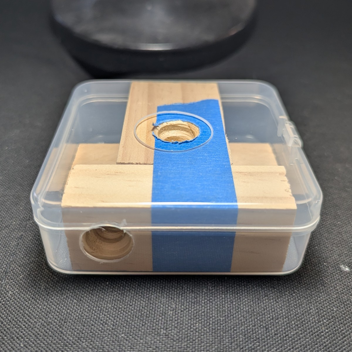
Drill the holes
Tape to the jar lid (see the Materials page) and drill the holes.
Drilling must be graduated and begin with a small drill bit. Too much force will crack the lid. Work up to a desired size using the step drill bit.
Line the inner rim
A spacer is needed to prevent the filter from contacting the cover. This allows air flow.
Cut a 11 mm x 335 mm strip of cardboard. Line the inner rim with the cardboard.
Attach retaining wire
The retaining wire locks the cover to the filter.
To make the retainer, drill holes on the side, about 60 degrees apart (or 110 mm * pi / 6 ~ 60 mm). Thread in some medium gauge electric wire, tie, and then trim. Wire must overhang the rim.
The completed cover
Final Assembly
Solder the USB connector
To supply battery power from the side opposite of the boost converter, we won’t be using the built-in USB ports.
Instead, solder the dangling USB port created in this step to the positive and negative input terminals of the boost converter.
Attach the boost converter
Attach the boost converter to the blower unit on the south side, with the USB-A port facing west. Use a combo of poster putty and masking tape.
For setting the boost converter, see the section on Testing the Blower.
Don’t use electrical tape – you’ll regret it.
Attach the hose
The hose is attached when flush against the retaining nut. The double barbs will not damage the soft silicone.
Ensure that both barbs are secure and that the hose will not come loose.
Secure the hose using about 15 cm (6 inches) of X-Fasten silicone tape.
Thread the blower unit into the case
Tape the adapter port so that debris doesn’t get inside during this step. Thread the hose through the case left. Thread the adapter port through the case front. Note the star shape formed by the seated adapter port.
(Case is shown upside down)
Put all the electronics inside. The angle adapter allows all the components to fit inside.
Fit the battery into the space on the case right with the USB port facing case top. Attach the blower unit USB port to the USB angle adapter. Attach the USB angle adapter to the battery.
Install the filter cover
This is optional.
To install the cover, wedge the edge of the filter pancake between the wire retainer and cardboard spacer. Pull the other wire retainer over the edge on the opposite side.
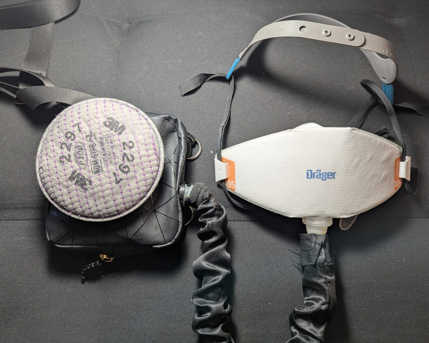
Connect to N95
Refer to this page for how to Attach to your N95 Mask
While it’s recommended to attach to the chin of a boat style N95, we’ve found that some folks are much more comfortable with the hose attached to the side of their mask. For bifold KN95s, this is mandatory. Do not attach over a seam since this significantly alters the fit.
And with that, the build is complete!
Use the rPAPR
Power the device
Connect the battery. If nothing comes on, press the button on the battery by the LED charge indicator. Check the voltage readout on the boost converter. If it reads zero, then press the on/off button on the boost converter, located near the read out.
The typical battery life of this design is 8 hours on medium flow (5.3 v), and 6 hours at high flow (5.7 v). For a full day at the office, you can keep a spare battery swap it out halfway through.
The battery may be swapped out without taking the mask off, since a well-sealed mask continues to protect during an unpowered state, as shown in the overview.
Put it on
The unit goes over the right shoulder
Adjust the strap
Adjust the strap.
A shorter strap increases the slack of the hose. When mounted, fully turn your head to the left, right, and upward. Check for tugging on the connection point to the mask, and tugging on the hose.
Tugging on the hose compromises safety by lifting/tugging on the connection point to your mask, compromising the seal. If you intend to use the mask for dance classes, concerts, or parties, the unit must be secured close to the center of your chest.
Don the mask
Put on your mask normally.
Enjoy your residential PAPR
And there it is!
The rPAPR in action:

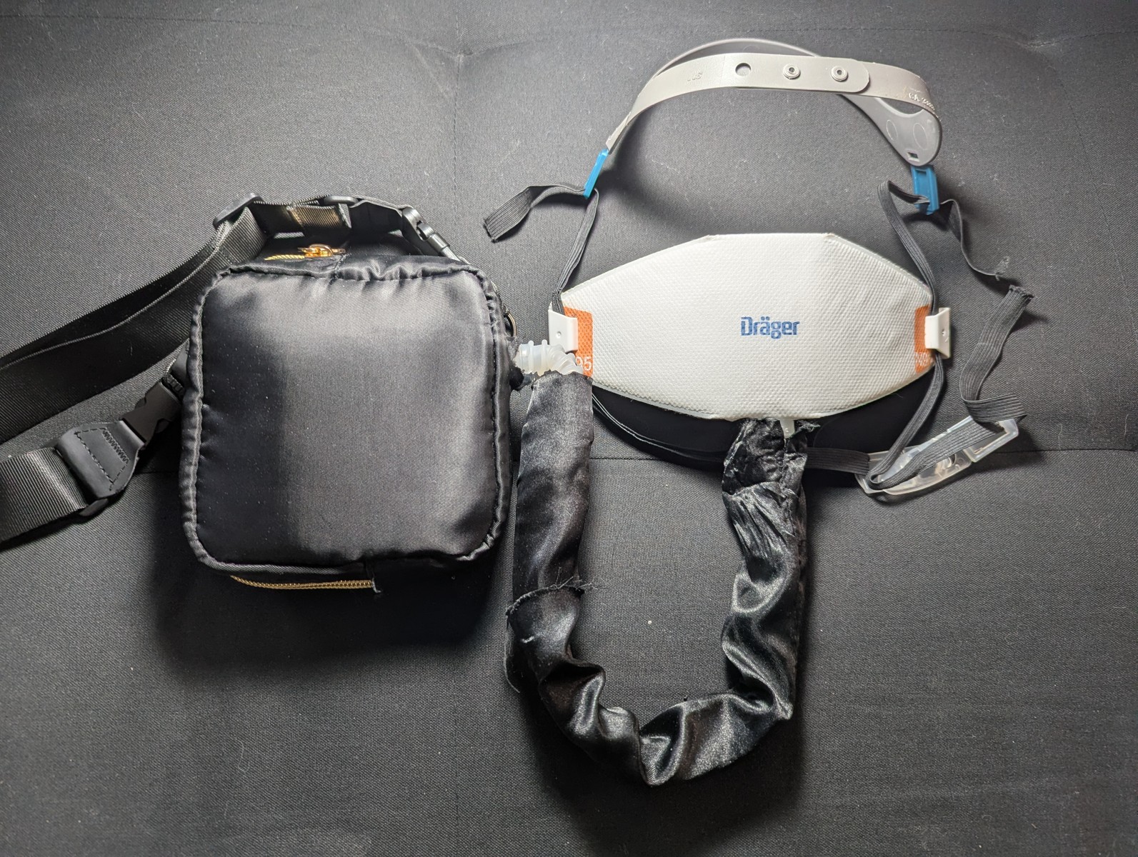
Bonus: connect to a half mask respirator
You can use your residential PAPR with a half mask elastomeric respirator for source control.
Moisture is the typical problem seen in source-controlled elastomerics.
To make this work, you have to remove the valve flaps. Elastomerics typically have three of them, two for the filters on inhale, and one for exhale.
Next you have to find an attachment point that covers the exhale.
The Honeywell North 7700 series is great for this, because you can easily remove the exhale valve, turn it around, reinstall it, and secure an acrylic disk with a hole drilled through it for the hose. A picture is provided without detailed instructions.
License
This work is licensed under the CERN Open Hardware Licence Version 2 - Permissive (CERN-OHL-P-2.0).
You may use, modify, and distribute this design, including for commercial purposes, provided that you retain attribution to the original author.
Need Help?
Send me an email at contact@maskingmatters.org, and I’ll be happy to consult.Did you enjoy this page? If so: Buy me a Coffee
Version History
- 2026-02-26 – v1.0.3 – Swap the filter and hose adapter install steps. Add extra blower test step.
- 2026-02-20 – v1.0.2 – Grammar and clarifications. More photos.
- 2026-02-18 – v1.0.1